Autofocusing method for telescopes pertaining to surveying equipment

Inactive Publication Date: 2003-05-15
TRIMBLE JENA
View PDF9 Cites 4 Cited by
  • Summary
  • Abstract
  • Description
  • Claims
  • Application Information

AI Technical Summary

Benefits of technology

[0012] For example, in the case of two-dimensional image detectors, it is advantageous to perform the calculations in the direction of the rows, in the direction of the columns or else in both directions at the same time.
[0013] It is likewise advantageous if the focusing path until the next measurement is ascertained as the product resulting from the ratio of the maximum signal to the local signal amplitude, from the focus position relative to the position during focusing towards the infinite and from a constant.
[0014] Moreover, it can be an advantage to provide an ideal edge as the comparison structure for the cross correlation function. It is likewise advantageous if the reference function is the maximum of the cross correlation function.

Problems solved by technology

This approach has the disadvantage that it cannot be easily transferred to a digital level.
This approach is likewise problematic.
This approach likewise does not necessarily ensure optimal image sharpness since the minimum can be relatively wide and therefore hard to detect.
The disadvantageous and complex aspect of this arrangement is the additional optical system that is needed.
This approach likewise entails drawbacks.
The entire procedure is impractical and complex.

Method used


Image

  • Autofocusing method for telescopes pertaining to surveying equipment
  • Autofocusing method for telescopes pertaining to surveying equipment
  • Autofocusing method for telescopes pertaining to surveying equipment

Examples


Embodiment Construction

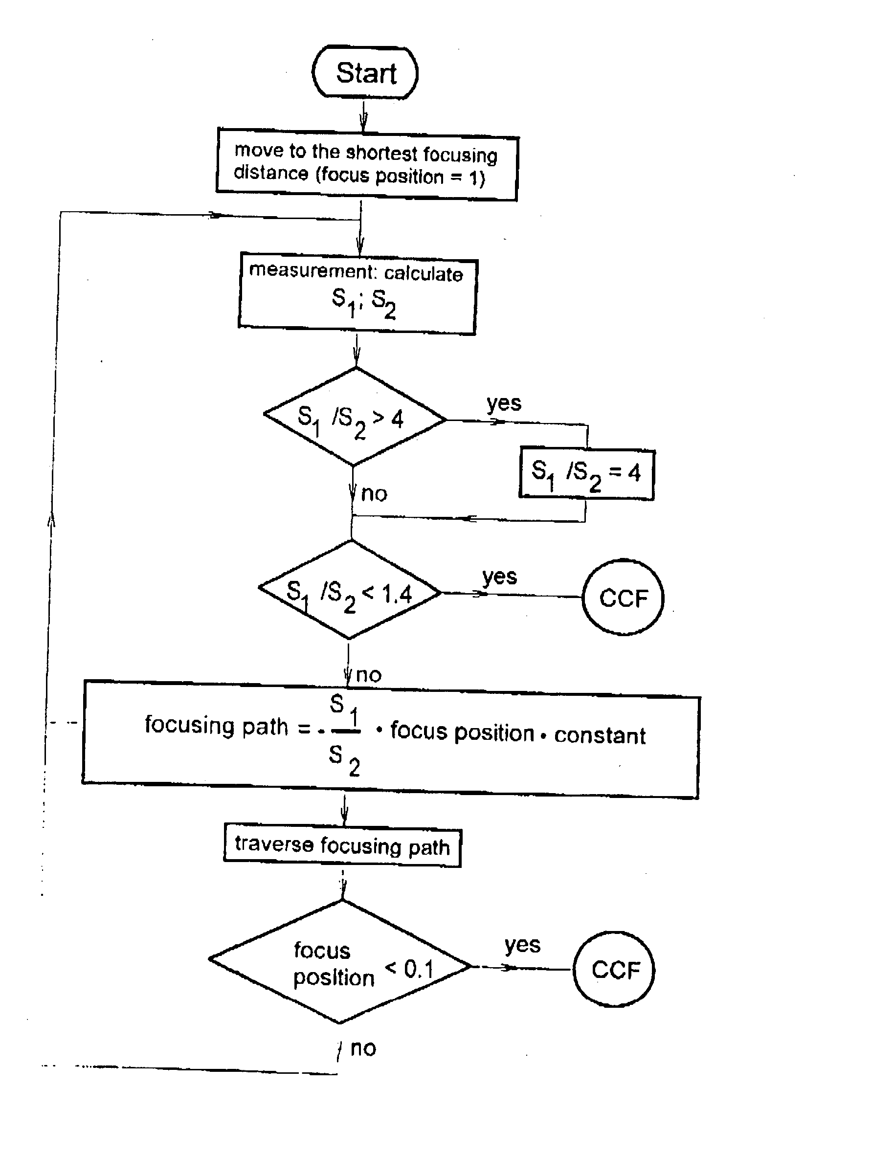
[0010] The objective of the present invention is to eliminate the disadvantages of the state of the art to the greatest extent possible so as to obtain an autofocusing control signal and to determine the point (state) of optimal focusing of the telescope without using additional optical means and without having to necessarily pass through the entire focusing range.

[0011] According to the invention, this objective is achieved with the means indicated in the first patent claim. The subordinate claims present details and embodiments of the invention.

[0012] For example, in the case of two-dimensional image detectors, it is advantageous to perform the calculations in the direction of the rows, in the direction of the columns or else in both directions at the same time.

[0013] It is likewise advantageous if the focusing path until the next measurement is ascertained as the product resulting from the ratio of the maximum signal to the local signal amplitude, from the focus position relative...


PUM


Abstract

The invention relates to an autofocusing method, particularly for telescopes for surveying instruments which are fitted with image sensors that resolve the image signal into individual image elements (pixels), such as CCD lines and / or matrices as well as CMOS image sensors. On the basis of the pixel that is located closest to the optical axis, the local signal amplitude is calculated from the monotonically decreasing or increasing signal all the way to the next local maximum and minimum. In this process, as long as this local signal amplitude is considerably smaller than the maximum signal and the focusing member of the telescope lens is in the focusing position for short focusing distances, this focusing member is shifted in large increments. Depending on the magnitude of the local signal amplitude, the focusing distance is shortened in the area of greater focusing distances in relation to the maximum signal and to the position of the focusing member. At a certain magnitude of the local signal amplitude in relation to the maximum signal, the cross correlation functions (CCF) are each additionally formed from several pixels of the signal and from suitable comparison structures and, at a certain ratio of a reference function formed on the basis of the CCF to the local signal amplitude, an increment range that is comparable to the optical depth of field is selected and focused to the maximum of the CCF.

Description

[0001] The invention relates to an autofocusing method, particularly for telescopes of surveying instruments, and it is suitable for image sensors that resolve the image signal into individual image elements (pixels), such as CCD lines and matrices as well as CMOS image sensors.STATE OF THE ART[0002] Autofocusing systems for surveying instruments are already known. German Preliminary Published Application DE-OS 196 14 235 describes an autofocus for a level. Here, an additional optical system located behind the focal plane serves to detect the sharp setting by means of two imaging lenses that generate object images on two line sensors. Moreover, means to detect the focusing lens position are necessary.[0003] German Preliminary Published Application DE-OS 195 49 048 should be seen in this context; by means of a beam splitter, a plane is generated that is equivalent to the focal plane for the focus detection system. This approach has the disadvantage that it cannot be easily transferre...

Claims


Application Information

Patent Timeline
IPC IPC(8): G01C1/02G01C15/00G02B7/36
CPCG01C1/02G02B7/36G01C15/002
Inventor MAROLD, THOMAS
Owner TRIMBLE JENA
Why Eureka
Try Eureka