High frequency oscillator using transmission line resonator
a transmission line resonator and high frequency oscillator technology, applied in the direction of oscillator, electrical equipment, etc., can solve the problems of increased circuit loss, low oscillation power, and difficulty in reducing cos
- Summary
- Abstract
- Description
- Claims
- Application Information
AI Technical Summary
Problems solved by technology
Method used
Image
Examples
first embodiment
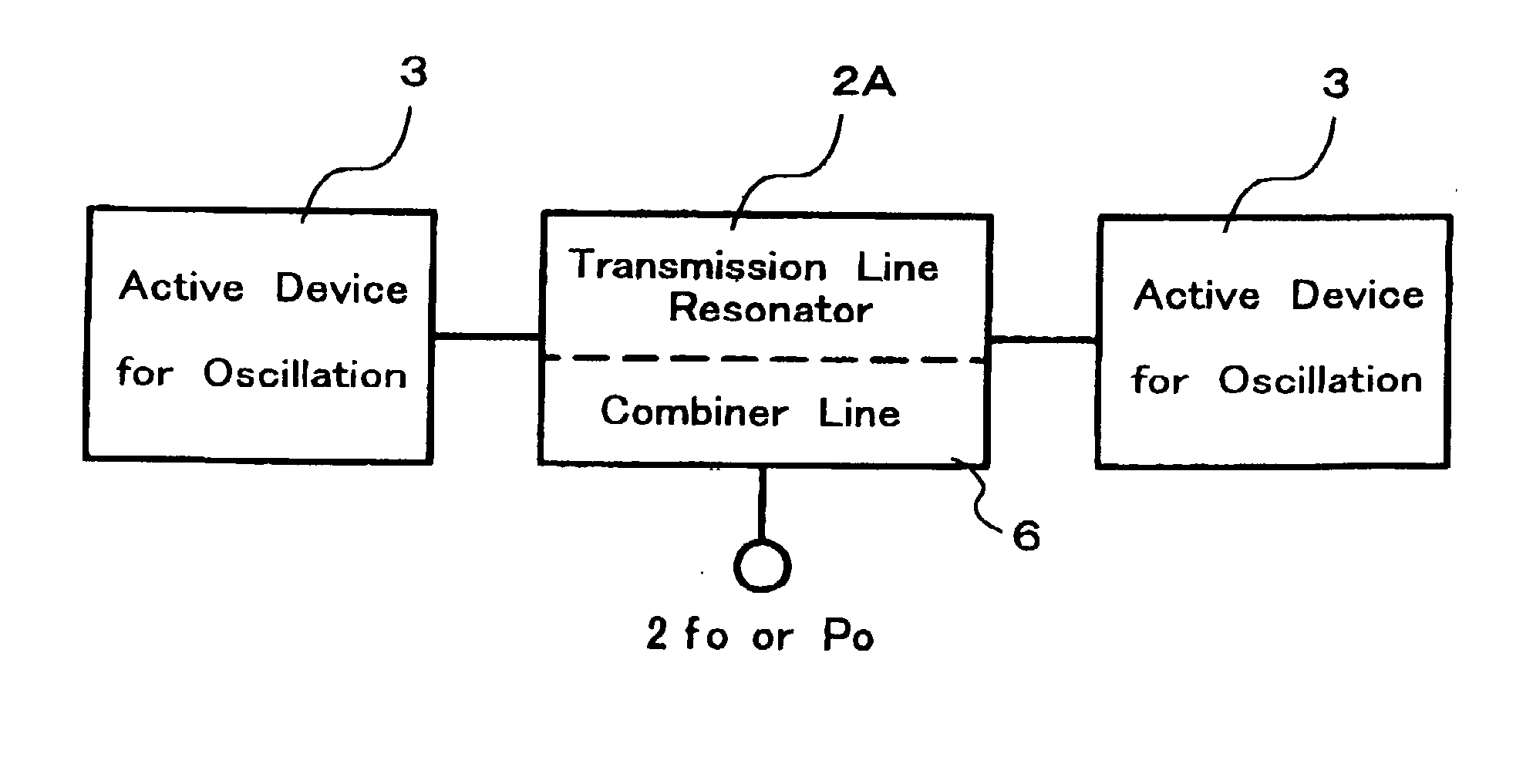
[0048] Referring next to FIGS. 5A and 5B, description will be made on a high frequency oscillator according to the present invention. Here, the high frequency oscillator is configured as a push-push oscillator.
[0049] On one principal surface of substrate 1 made of a dielectric material, an elongated linear line having a length of .lambda. / 2 and a predetermined width is routed as a signal line, where .lambda. represents the wavelength corresponding to oscillation frequency (fundamental wave) f.sub.0. Ground conductor 8 is formed substantially over the entirety of the other principal surface of substrate 1. The signal line, together with ground conductor 8, forms line resonator 2A having a microstrip line structure. Line resonator 2A is a transmission line resonator. In addition, two active devices 3 for oscillation and combiner line 6 having a microstrip line structure are provided on the one principal surface of substrate 1.
[0050] FETs are employed for both of two active devices 3 f...
second embodiment
[0060] Likewise, in the second embodiment, a microstrip line having a line length of .lambda. / 4 may be connected to the midpoint of line resonator 2A to permit the high frequency oscillator to perform more stable antiphase oscillation, as is the case with the circuit configuration illustrated in FIG. 6. In addition, combined output P.sub.o may be directly generated in balanced mode from combiner line 6 which is formed of a slot line routed on the other principal surface of substrate 1.
third embodiment
[0061] Referring next to FIG. 8, description will be made on a high frequency oscillator according to the present invention. This high frequency oscillator is a push-push oscillator similar to that illustrated in FIGS. 5A and 5B, but differs in that ring resonator 2B is used for a transmission line resonator.
[0062] The high frequency oscillator according to the third embodiment comprises ring resonator 2B; two active devices 3; and combiner line 6. A signal line is circularly routed on one principal surface of substrate 1 made of a dielectric material or the like. This signal line forms ring resonator 2B in microstrip line structure, together with a ground conductor deposited substantially over the entirety of the other principal surface of substrate 1. The circular signal line of ring resonator 2B has a line length .lambda., where .lambda. represents the wavelength corresponding to an oscillation frequency (i e. fundamental wave f.sub.0).
[0063] FETs are employed for two active devi...
PUM
 Abstract
Description
Claims
Application Information
 - R&D
- Intellectual Property
- Life Sciences
- Materials
- Tech Scout
- Unparalleled Data Quality
- Higher Quality Content
- 60% Fewer Hallucinations
Browse by: Latest US Patents, China's latest patents, Technical Efficacy Thesaurus, Application Domain, Technology Topic, Popular Technical Reports.
© 2025 PatSnap. All rights reserved.Legal|Privacy policy|Modern Slavery Act Transparency Statement|Sitemap|About US| Contact US: help@patsnap.com


