Polymer fuel cell structure

a fuel cell and polymer technology, applied in the field of fuel cells, can solve the problems of water management, cell components, and prone to dry membranes, and achieve the effect of improving the conductivity of the membrane, facilitating cell operation, and reducing the number of polymer fuel cells

Inactive Publication Date: 2003-05-15
POWERCELL SWEDEN AB
View PDF6 Cites 13 Cited by
  • Summary
  • Abstract
  • Description
  • Claims
  • Application Information

AI Technical Summary

Benefits of technology

[0012] Despite the numerous attempts to improve the water management in polymer fuel cells, there is still room for improvements. Thus, an object of the present invention is to provide means for achieving better humidification, at low cost and with low cell complexity. The trade-off between performance and cost should be acceptable.
[0014] By way of the present invention, it is possible to maintain a direct water contact with the membrane at the anode side. This is beneficial for the operation of the cell, since the water content and the conductivity of the membrane are much higher when the membrane is in equilibrium with water. Also, when water is evaporated inside the fuel cell, a considerable amount of the heat that is produced in the cell can be removed from the cell by means of the produced water vapor.

Problems solved by technology

Serious problems, however, are encountered when polymer fuel cell technology is scaled up to larger cells and stacks.
One of the main problems, in the stacks themselves, is the water management, since the proton conducting membrane must be kept well humidified under operating conditions.
Membranes tend to dry out, especially on the anode side, at high current densities, since proton migration drags water molecules away from the anode.
Therefore, in attempts to remedy this problem the anode side is often humidified more intensively than the cathode side.
One solution for this problem would be to use thinner membranes, but this approach has limitations since mechanical rigidity of the membrane must be sufficient.

Method used


Image

  • Polymer fuel cell structure
  • Polymer fuel cell structure
  • Polymer fuel cell structure

Examples


Embodiment Construction

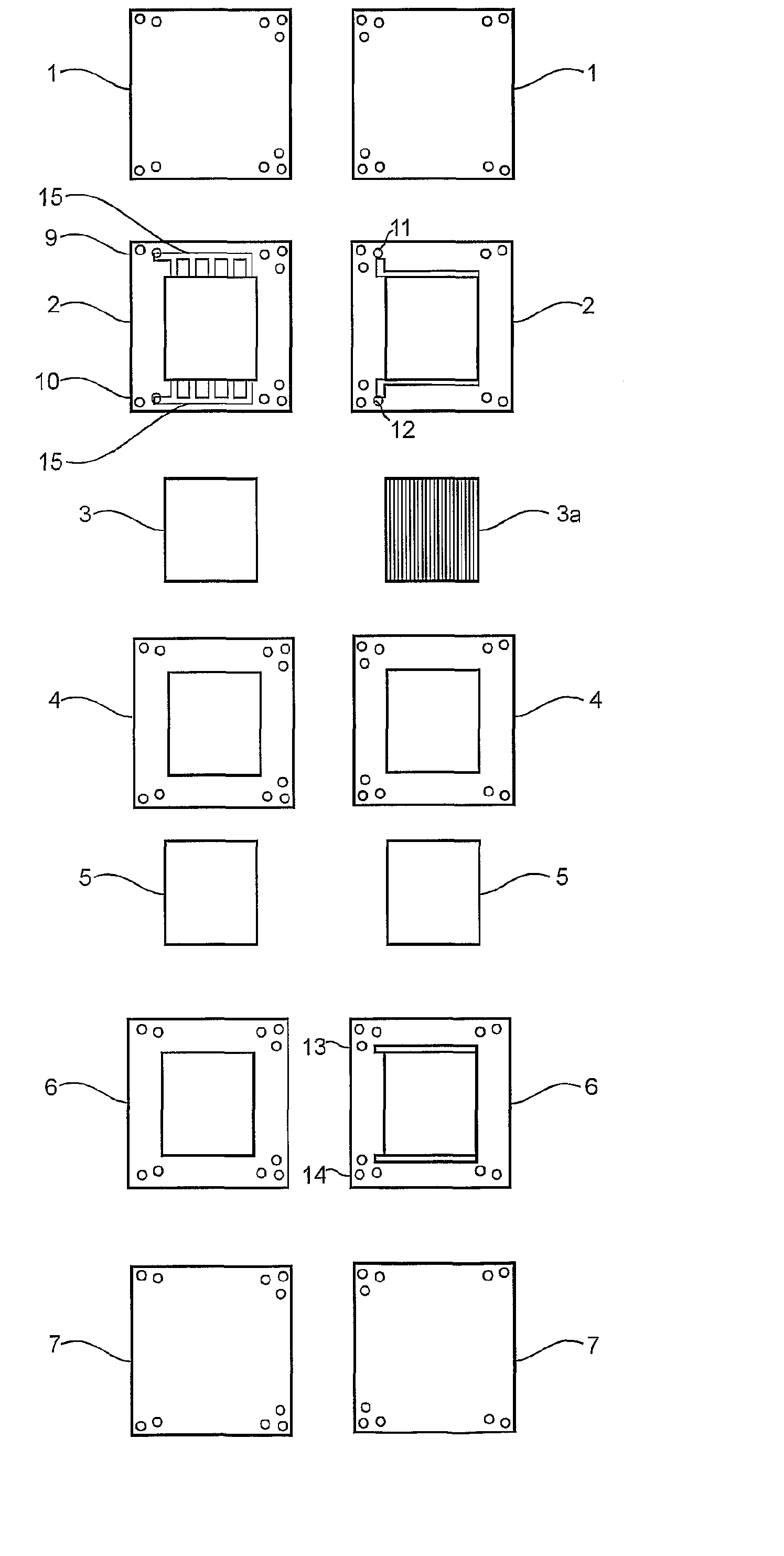
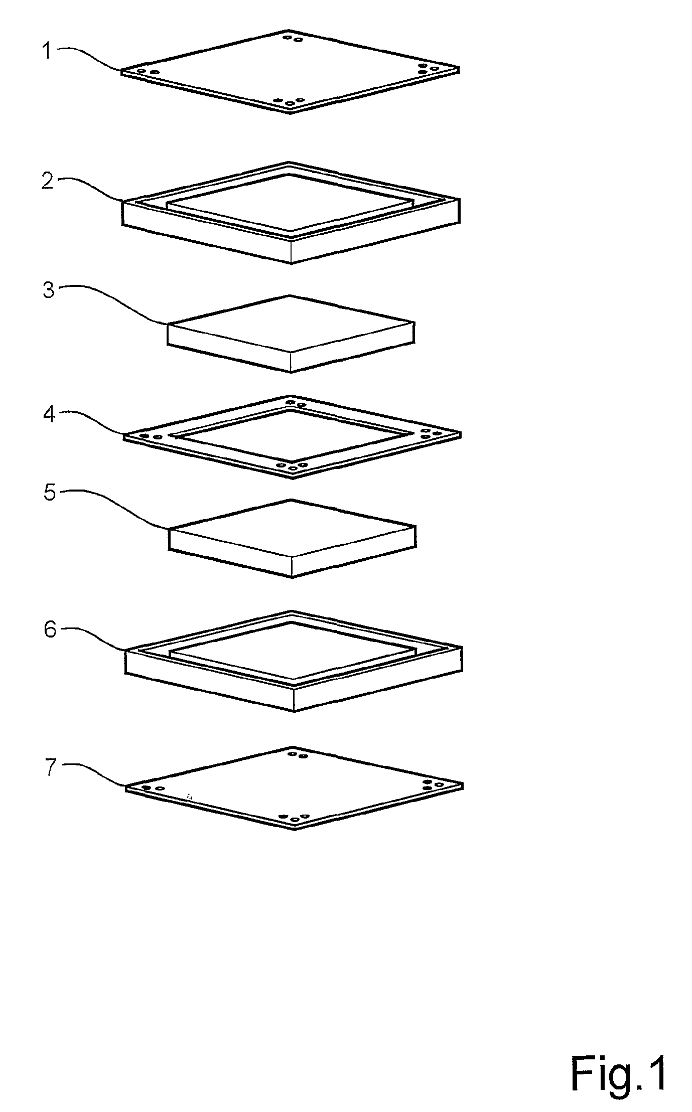
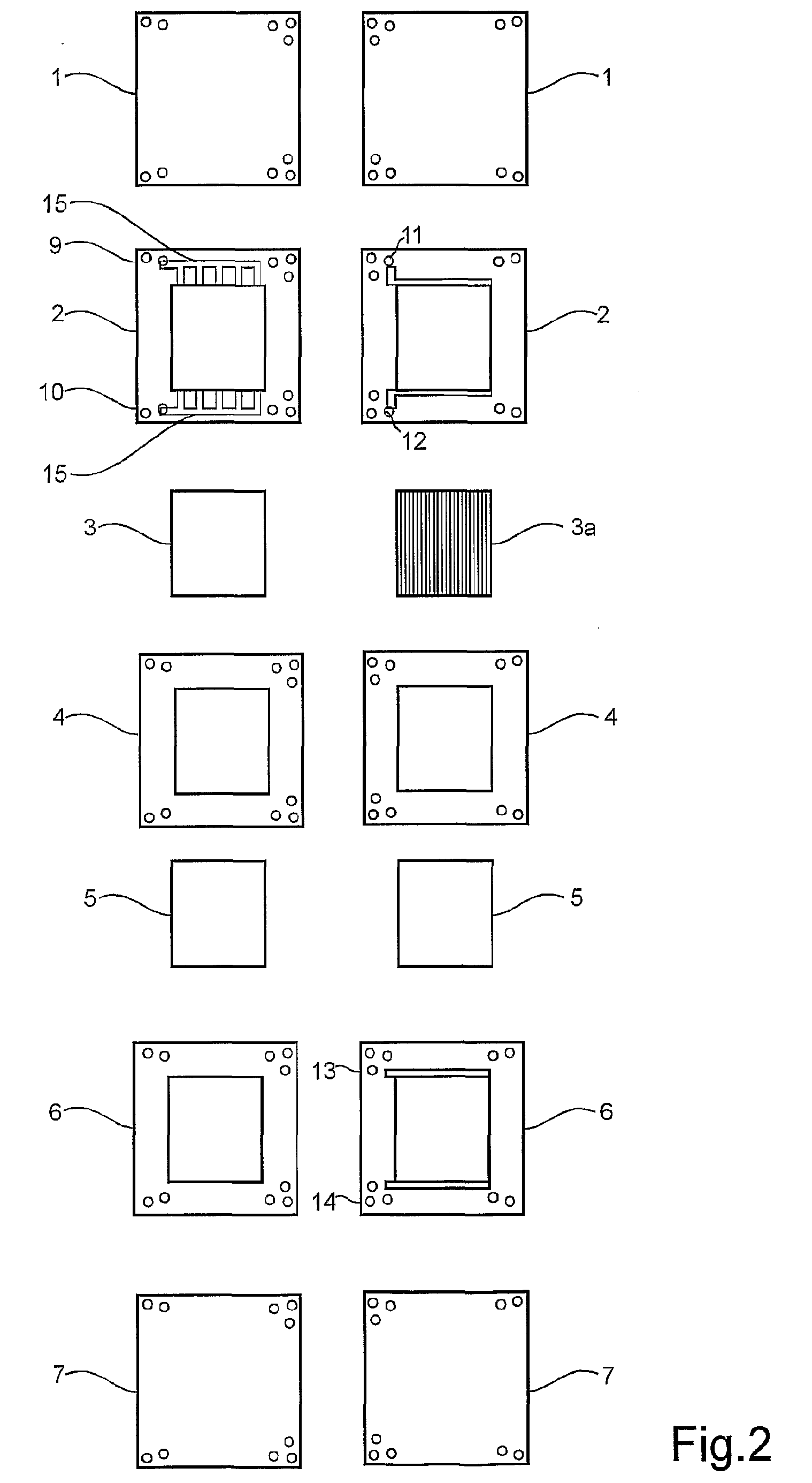
[0023] A preferred embodiment of the fuel cell structure according to the present invention is shown in figure 1 and 2. The fuel cell includes a conductive anode plate 1. An anode sealing frame 2 is provided adjacent the bipolar plate 1. This frame is provided with a central, rectangular opening for an anode gas distribution layer 3. The frame 2 is also provided with an anode gas inlet 9 and an outlet 10 and distribution channels are formed as well as water inlets and outlets 11, 12 respectively. The anode gas distribution layer 3 is provided with a plurality of narrow water channels 3a on the opposite side of the layer 3, with reference to the anode plate 1. A proton exchange membrane 4 is arranged for cooperation with the plate 1 for sandwiching the frame 2 and the diffusion layer 3 between themselves.

[0024] The cathode side of the fuel cell is structured in a similar manner as the anode side. Thus, the opposite side of the membrane 4 is arranged for cooperation with a conductive ...


PUM

PropertyMeasurementUnit
widthaaaaaaaaaa
depthaaaaaaaaaa
distanceaaaaaaaaaa

Abstract

Abstract of Disclosure A polymer electrolyte fuel cell structure includes a proton exchange membrane (4). An anode catalyst layer (1,16) is located on one side of the proton exchange membrane. A cathode catalyst layer (7) is located on the opposite side of the proton exchange membrane, and a gas distribution layer (3,5) is arranged on each side of the proton exchange membrane (4). The anode side gas distribution layer (3) is a flat, porous structure having water channels (3a) formed in the surface facing the membrane (4). The anode side gas distribution layer (3) is enclosed by a coplanar, sealing plate (2) with water inlet channels coupled to the water channels (3a) in the gas distribution layer.

Description

Cross Reference to Related Applications[0001] The present application is a continuation patent application of International Application No. PCT / SE01 / 01514 filed 29 June 2001, published in English pursuant to PCT Article 21(2) and which claims priority to Swedish Application No. 0002601-3 filed 7 July 2000. Both applications are expressly incorporated herein by reference in their entireties.Background of Invention[0002] TECHNICAL FIELD: The present invention generally relates to fuel cells; and more particularly, to improvements in performance of polymer fuel cells.[0003] BACKGROUND OF THE INVENTION: Polymer fuel cells are on the fringe of commercialization. The progress made in catalyst and membrane research in the last few years has enabled very high power densities (>1W / cm.sup.2) with moderate efficiencies for the fuel cell (40%). The catalyst loading of electrodes has been reduced to 0.1 mg Pt / cm.sup.2 while maintaining a high performance. The price of the perfluorinated sulf...

Claims


Application Information

Patent Timeline
Patent Type & Authority Applications(United States)
IPC IPC(8): H01M8/02H01M8/04H01M8/06H01M8/10
CPCH01M8/0245H01M8/026H01M8/0263H01M8/0273H01M8/04029Y02E60/50H01M8/04291H01M8/1004H01M8/1009Y02E60/523H01M8/04119
Inventor IHONEN , JARIJAOUEN , FREDERIC
Owner POWERCELL SWEDEN AB
Why Eureka
Try Eureka