Multi-bladed surgical scalpel

a surgical scalpel and multi-blade technology, applied in the field of multi-bladed surgical scalpels, can solve the problems of increasing post-surgical facial swelling, affecting the treatment effect, and reducing the amount of time a transplant patient has to make all the necessary incisions, so as to reduce the amount of time a transplant patient spends, the effect of easy control of the depth

Inactive Publication Date: 2003-05-22
MITTELSTAEDT MARK
View PDF8 Cites 26 Cited by
  • Summary
  • Abstract
  • Description
  • Claims
  • Application Information

AI Technical Summary

Benefits of technology

0012] With conventional single-bladed knives, a separate stroke is required to make each incision. Painstaking care must be taken to locate each incision at the desired location, make each incision to the desired depth, and align each incision such that it is made at the proper angle into the scalp. In surgery, this process is very time consuming. With multi-bladed scalpels, the amount of time required to make all the necessary incisions is greatly reduced. This reduces the amount of time a transplant patient has to spend under anesthesia.
0013] In one embodiment of this design, an adjustable depth gauge is built into the handle of the knife. This allows the surgeon to set a uniform penetration depth, making it very easy to control the depth of each incision. Incisions that are too deep increase bleeding. They result in more post-surgical facial swelling, and take longer to heal. Graft compression may occur when an individual graft is too large for an incision. Grafts are often rejected from too-shallow incisions. Incisions that are too shallow are less effective at providing sufficient volume to insert follicular units.
0014] Since incision depth and alignment are of such importance, a surgeon needs to be very painstaking with each incision. To provide a natural appearance, the incisions often need to be less than one millimeter / 0.040" apart. Such precise cuts quickly result in hand fatigue, and introduce the potential for repetitive stress injury to the surgeon. With the depth gauge, and with multiple cuts being made in one stroke, the percentage of cuts made at the ideal depth, spacing and alignment will greatly increase, thus increasing donor hair "yield"--the number of grafts that "take", with minimum patient discomfort.
0015] In various embodiments of this invention, different numbers of blades are used, and spacing between the blades is changed, to provide varying incision density. This allows the surgeon to more closely match the number of incisions with coverage area desired and amount of donor hair available.
0016] Also, in various embodiments, the blade tips are mounted at varying angles. This allows the blade tips of a multi-bladed tool to make their individual incisions at the same time when the tool is held at the corresponding angle. Various blade angles provide a tool that can be used at an angle ergonomically suited to the individual surgeon.
0017] These multi-bladed scalpels are inexpensive to manufacture. They require no learning curve to use, or technician to operate. They give the surgeon more time in the time-critical part of the surgery. They decrease hand fatigue, so all incisions can be made more carefully and precisely. The parallel blades provide very repeatable incision spacing and alignment--one incision does not occur too close to another, so capillary revascularization around each follicle is maximized, and post-operative swelling and bleeding are minimized.

Problems solved by technology

In surgery, this process is very time consuming.
Incisions that are too deep increase bleeding.
They result in more post-surgical facial swelling, and take longer to heal.
Graft compression may occur when an individual graft is too large for an incision.
Incisions that are too shallow are less effective at providing sufficient volume to insert follicular units.
Such precise cuts quickly result in hand fatigue, and introduce the potential for repetitive stress injury to the surgeon.

Method used


Image

  • Multi-bladed surgical scalpel
  • Multi-bladed surgical scalpel

Examples


Embodiment Construction

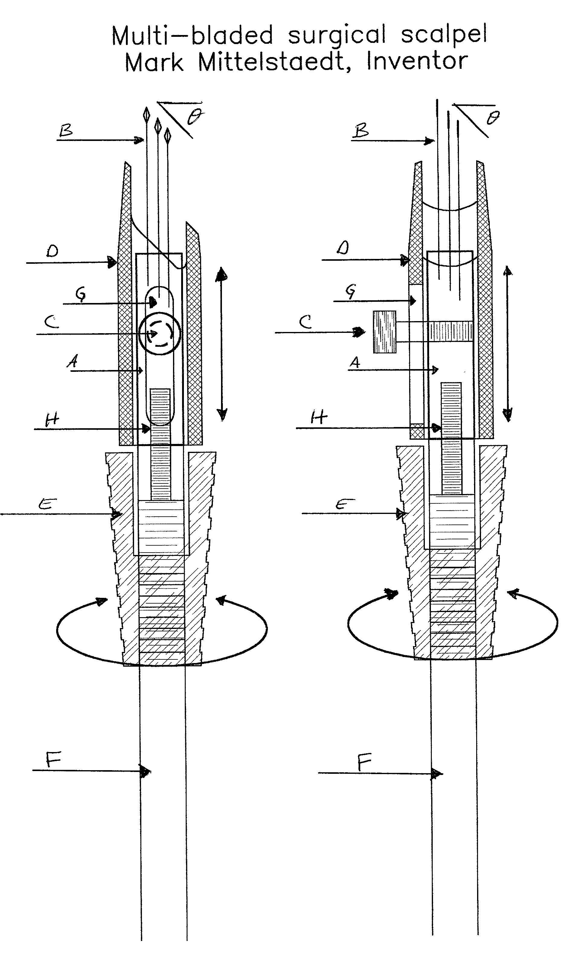
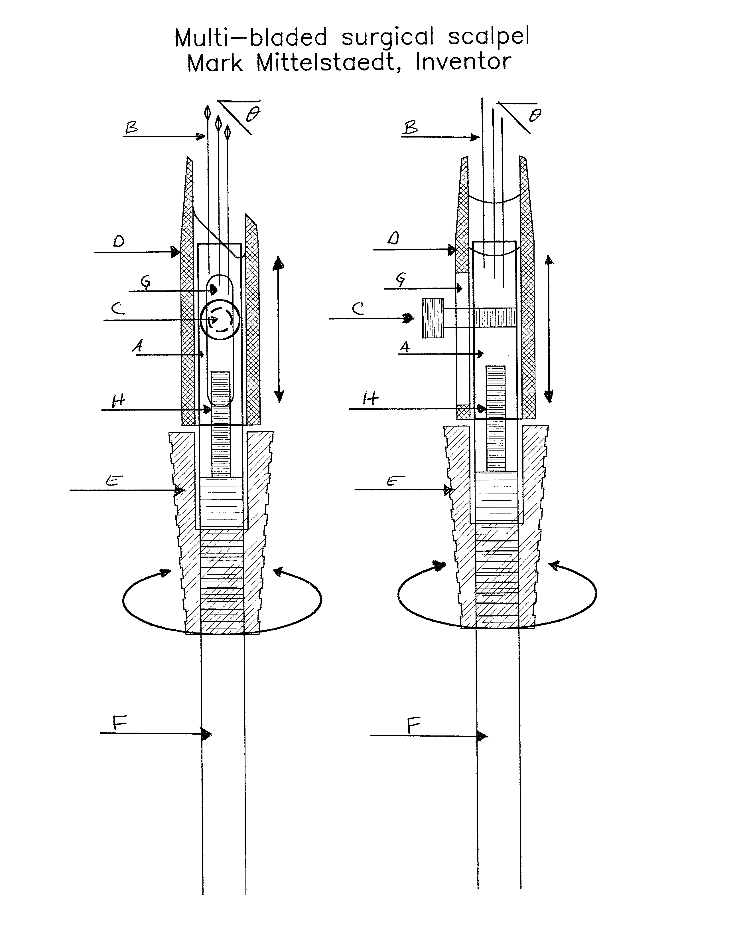
[0022] There was nothing like this, so I started from scratch. There were no inventions that allowed for blade mounting close enough such that one area of scalp could be incised for hair transplantation purposes, then the tool moved to an adjacent area to repeat the process. In this embodiment, the blade holder is machined from Delrin, and all the other parts from aluminum, although newer versions might use different materials.

[0023] The blade holder is machined from medical grade Delrin, using {fraction (1 / 4)}" diameter, 1" long sections. These sections are machined to provide an orientation flat along the top 0.1" of a vertically oriented section. Blade holes are then drilled into the top such that the angle of the plane defined by the blade tips is ergonomically desirable angle--in this case, 45 degrees. The blade holes get deeper as they are drilled from left to right to achieve this angle. The orientation flat is parallel with this left--right line. 4.times.40 holes are then ta...


PUM


Abstract

This multi-bladed scalpel addresses the problem of making many small incisions in very close proximity (as close as 0.030''/0.75 mm) to each other, to facilitate hair transplantation. With this device, it is possible to make multiple incisions in such proximity. With the blades mounted parallel to each other, at the desired spacing, each incision does not intersect neighboring incisions, so the follicles placed in each incision will be surrounded by the maximum amount of undisturbed tissue to promote revascularization-capillary growth to provide a blood supply to each transplanted follicle. CNC machining techniques are used to create the blade holders with blade mounting sites created at the desired proximity. Medical grade epoxy is used to mount the blades, which are mounted parallel to each other. Holes are drilled so the tips of the blade group are located in a plane at an angle with respect to the blade holder for ergonomic reasons

Description

[0001] This multi-bladed surgical scalpel was created to facilitate hair transplantation. In this process, it is necessary to make a series of incisions in very close (as close as 0.030" spacing between neighboring blades) proximity to each other, so hair follicles can be placed in each incision where they will then take root and grow hair.[0002] In this embodiment, the blade holder is made from a section of Delrin rod, one inch long by {fraction (1 / 4)}" in diameter. A series of holes just slightly (0.001"-0.003") larger than the blade shaft diameters is drilled into the circular end face of the section. The holes are drilled such that the tips of all the blades are in the same plane, such plane to be at a desired angle to the end face of the section. A shallow (0.030") orientation flat is machined on the side of the section for 0.10" from the end face of the section into which the holes are drilled. The blades are mounted with medical grade epoxy, and oriented such that they are pa...

Claims


Application Information

Patent Timeline
Patent Type & Authority Applications(United States)
IPC IPC(8): A61B17/32A61F2/10
CPCA61B17/32093A61F2/10A61B2017/00752A61B17/3211
Inventor MITTELSTAEDT, MARK
Owner MITTELSTAEDT MARK
Why Eureka
Try Eureka