
Piezoelectric filter, communication device, and method for manufacturing communication device

a technology of communication device and piezoelectric filter, which is applied in piezoelectric/electrostrictive transducers, device material selection, generators/motors, etc., can solve problems such as difficult to achieve, deterioration of resonator characteristics, and inability to readily increase productivity

Inactive Publication Date: 2003-05-29
MURATA MFG CO LTD
View PDF7 Cites 14 Cited by
  • Summary
  • Abstract
  • Description
  • Claims
  • Application Information

AI Technical Summary

Benefits of technology

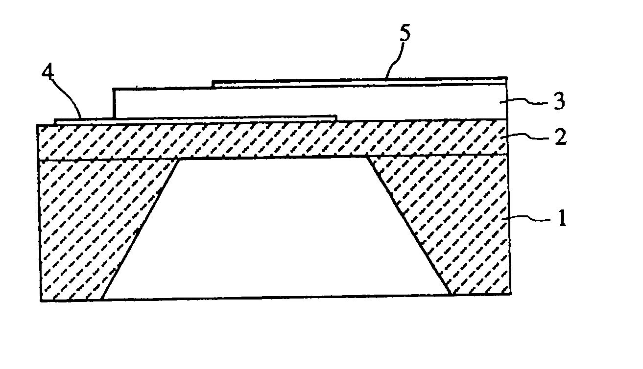
[0012] Since the lower electrodes of the piezoelectric resonator portions formed in the above-described manner have a thickness that is larger than that of the upper electrode, the thickness of the entire resonant region is increased and the mass is accordingly increased, thereby lowering the resonant frequency.
[0026] Since the upper and lower electrodes are in contact with the piezoelectric thin-film, change in the resonant frequency with respect to the thickness of the upper and lower electrodes can be increased. Therefore, the ratio of the thickness of the piezoelectric thin-film to the thickness of the upper or lower electrodes is not significantly changed, and the temperature characteristics of the resonant frequency of piezoelectric resonator portions having a relatively low resonant frequency and other piezoelectric resonator portions are not significantly changed, thereby obtaining the stable filter characteristics against change in temperature.

Problems solved by technology

Therefore, the selectivity of the film formation must be improved but it is difficult to do so which presents a significant problem.
Therefore, there is a problem in that the productivity cannot be readily increased.
Therefore, there is a risk that the characteristics of the resonator are deteriorated.
On the other hand, in the configuration disclosed in U.S. Pat. No. 5,910,756, since it is difficult to widely control the resonant frequency with respect to the thickness of the SiO.sub.2 layers, the second SiO.sub.2 layer must have a certain thickness in order to obtain a desired difference between the frequency of resonators connected in parallel and that of resonators connected in series when a ladder filter is prepared.
Therefore, there is a problem in that the filter characteristics are significantly changed.

Method used


Image

  • Piezoelectric filter, communication device, and method for manufacturing communication device
  • Piezoelectric filter, communication device, and method for manufacturing communication device
  • Piezoelectric filter, communication device, and method for manufacturing communication device

Examples


Embodiment Construction

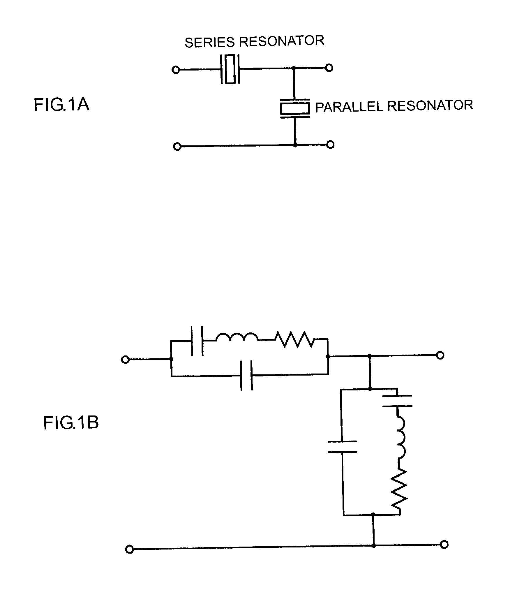
[0094] FIG. 9 shows another ladder-type piezoelectric filter including first, second, and third parallel resonators 101, 103, and 105, and first and second series resonators 102 and 104. The first parallel resonator 101 and the first series resonator 102 commonly have a fourth upper electrode 207, the second series resonator 104 and the third parallel resonator 105 commonly have a fifth upper electrode 208, and the second parallel resonator 103 has a sixth upper electrode 209. The first, second, and third parallel resonators 101, 103, and 105 have first, second, and third parallel lower electrodes 307, 309b, and 308, respectively. The first and second series resonators 102 and 104 commonly have a series lower electrode 309a. The fourth, fifth, and sixth upper electrodes 207, 208, and 209 have the same thickness. The first, second, and third parallel lower electrodes 307, 309b, and 308 have the same thickness larger than that of the series lower electrode 309a.

[0095] In the first pre...


PUM

PropertyMeasurementUnit
Thicknessaaaaaaaaaa
Frequencyaaaaaaaaaa
Piezoelectricityaaaaaaaaaa

Abstract

A piezoelectric filter includes a plurality of piezoelectric resonator portions each having a substrate, an SiO2 layer, a piezoelectric thin-film, a lower electrode, and an upper electrode. The plurality of piezoelectric resonator portions include piezoelectric resonator portions having a relatively low frequency, and the lower electrodes of the piezoelectric resonator portions having a relatively low frequency have a thickness larger than that of lower electrodes of other piezoelectric resonator portions. A ladder-type piezoelectric filter, which is one of the communication devices, includes a plurality of parallel resonators and series resonators.

Description

[0001] 1. Field of the Invention[0002] The present invention relates to a piezoelectric filter including a piezoelectric resonator having a substrate, such as a silicon wafer, and a piezoelectric thin-film disposed on the substrate, and also relates to a communication device and a method for manufacturing the piezoelectric filter.[0003] 2. Description of the Related Art[0004] Piezoelectric resonators having a substrate, such as a silicon wafer, and a piezoelectric thin-film disposed on the substrate are disclosed in Japanese Unexamined Patent Application Publication No. 58-121815 and U.S. Pat. No. 5,910,756.[0005] A piezoelectric resonator disclosed in Japanese Unexamined Patent Application Publication No. 58-121815 has a substrate having a recessed portion, a piezoelectric thin-film having a pair of electrodes and disposed on a surface of the substrate, and a frequency-adjusting thin-film disposed in the recessed portion located on the back of the surface of the substrate and locat...

Claims


Application Information

Patent Timeline
IPC IPC(8): H01L41/08H01L41/09H01L41/18H01L41/22H01L41/29H03H3/02H03H3/04H03H9/02H03H9/17H03H9/58H03H9/60
CPCH03H3/04H03H9/174Y10T29/42H03H2003/0428H03H2003/0471H03H9/605
Inventor TAKEUCHI, MASAKIKAWAMURA, HIDEKI
Owner MURATA MFG CO LTD
Learn More