Support structure for trellis system

a technology of supporting structure and trellis, which is applied in the direction of machine supports, other domestic objects, mechanical apparatus, etc., can solve the problems of large cost of the supporting structure itself, high cost of installing and maintaining the trellis system in the field, and the existing trellis structur

Inactive Publication Date: 2003-06-05
A&P STRUCTURES
View PDF0 Cites 14 Cited by
  • Summary
  • Abstract
  • Description
  • Claims
  • Application Information

AI Technical Summary

Benefits of technology

[0012] The structure of the present invention is produced by first bending the central section of a metallic support member (such as a studded T-post) into a U-shape using an appropriate hydraulic press or other suitable pressure imparting machine. The tools and settings used on the machine should be set so as to apply pressure broadly to the metallic member at its center to form the shape of a modified "U." The forming pressure is not applied to a single point that might otherwise form an undesirable "V." A broad, blunt tool shape is preferable, the width of the tool being selected according to the overall size of the metallic member to be bent, the desired angle between the resulting arms, and the length of the desired bow at the bottom of the "U." Only enough pressure to bend the metallic member into a modified "U" shape should be applied. The angle between the arms may be anywhere from 46.degree. to 179.degree. (i.e., each arm being raised from 1.degree. to 67.degree. from horizontal), preferably in a range of between 100.degree. and 130.degree. (i.e., each arm being raised from 25.degree. to 40.degree. from horizontal). Thereafter, the bent member, now having two angled arms, is placed on a specially designed jig. The jig has a plurality of adjustable guides that are pre-set according to the angle desired between the arms of the metallic member. Inserting the bent member into these guides assures that the arms meet the exact pre-set angle. Thereafter, a cross arm is attached between the two arms, one end to each arm. Attaching the cross arm locks in the angle of the arms, and prevents this angle from changing. The combined structure is then attached to a vertical support member, with an attachment at the center of the U, and another attachment at the center of the cross arm. This prevents pivotal rotation of the combined structure once it is mounted on the support post.
[0013] It is therefore a primary object of the present invention to provide a strong and reliable support structure for use in an agricultural trellis system having a support member in the shape of a modified "U" defining a pair of angled support arms, and a cross member attached to and extending between the support arms, in which the support member and cross arm are attached to a post.
[0014] It is also a primary object of the present invention to provide a method for consistently manufacturing a support structure for use in an agricultural trellis system having a support member in the shape of a modified "U" defining a pair of angled support arms, and a cross member attached to and extending between the support arms for attachment to a post.

Problems solved by technology

Existing trellis structures suffer from a number of common deficiencies including, most notably, the great expense of the support structures themselves, as well as the high cost of installing and maintaining the trellis system in a field.
The installation process is complex, involving precise positioning of the support structures and wires, requiring specially trained and more costly labor for proper installation.
After installation, there are continuing costs associated with maintaining and adjusting the tension of the wires and the positions of the support structures on a regular basis, particularly as the weight on the system is increased due to plant growth and the weight of annual crops.
However, such angled support arms are generally formed from inexpensive T-stakes (T-posts) which are notorious for inconsistencies and lack of lateral straightness, resulting in inconsistencies from one support structure to the next in a field.
This leads to an inconsistent appearance in the field, potentially inconsistent crop support, and increased maintenance costs.
In addition to being expensive, trellis structures are continuously subjected to the rigors of their outdoor environment.
The more elaborate the design of the trellis system, the more significant and expensive these factors can be.
This structure suffers from several drawbacks including significant stress on the central V-bend in the cross member from the great weight of the plants and crops supported.
Because of this weight, the single V-shaped member is susceptible to fatigue and early failure.
Moreover, the single central attachment coupling between the support post and the V-shaped cross member may act as a pivot, allowing the cross member to move relative to the post, resulting in cross members of adjacent supports to fall out of alignment with each other, thereby requiring frequent adjustments of the structures and the wires they support.
The manufacturing of this trellis structure is prone to inconsistent production results that become apparent upon installation in the field, and the installation process itself is inefficient and subject to irregularities and inconsistencies.

Method used


Image

  • Support structure for trellis system
  • Support structure for trellis system
  • Support structure for trellis system

Examples


Embodiment Construction

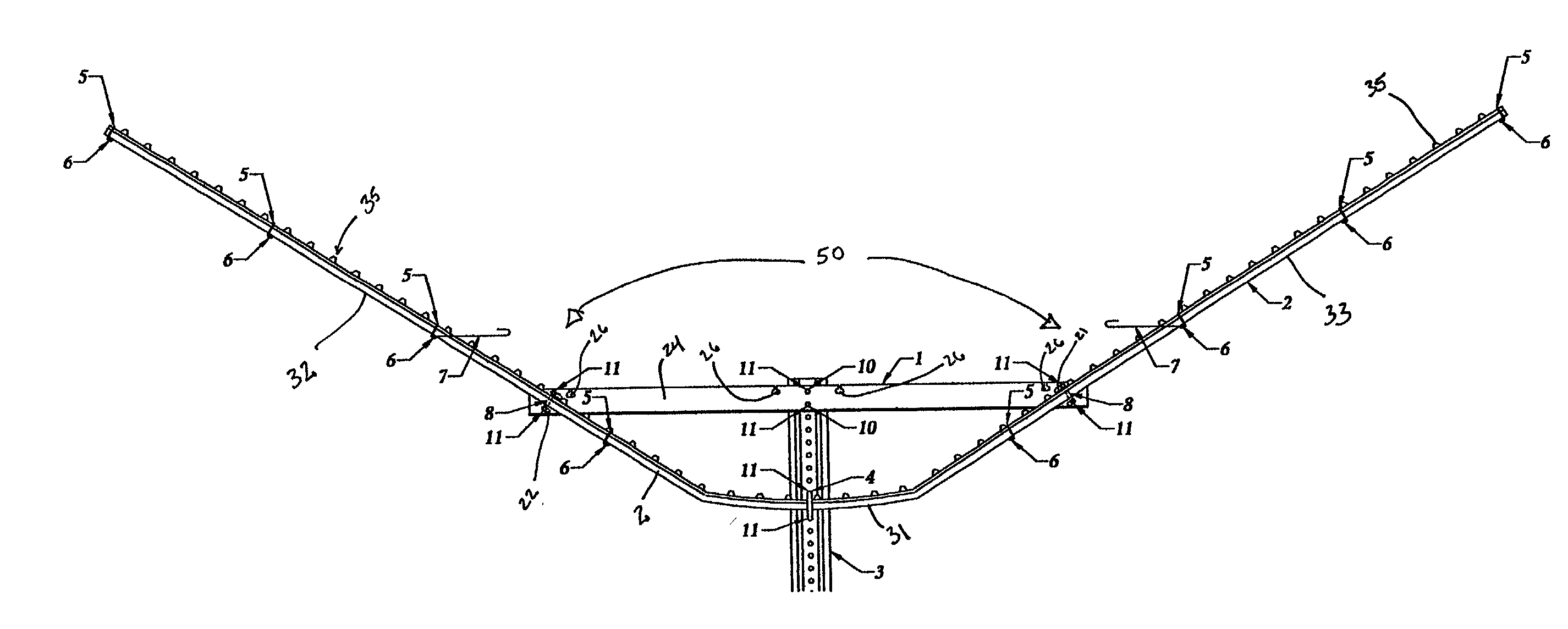
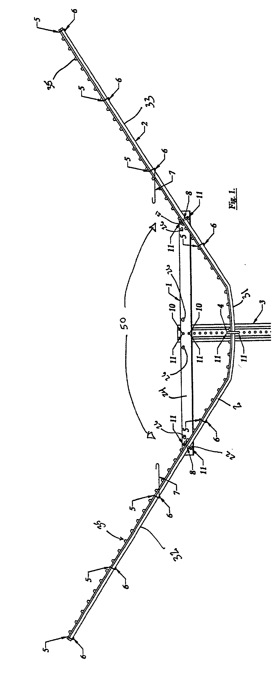
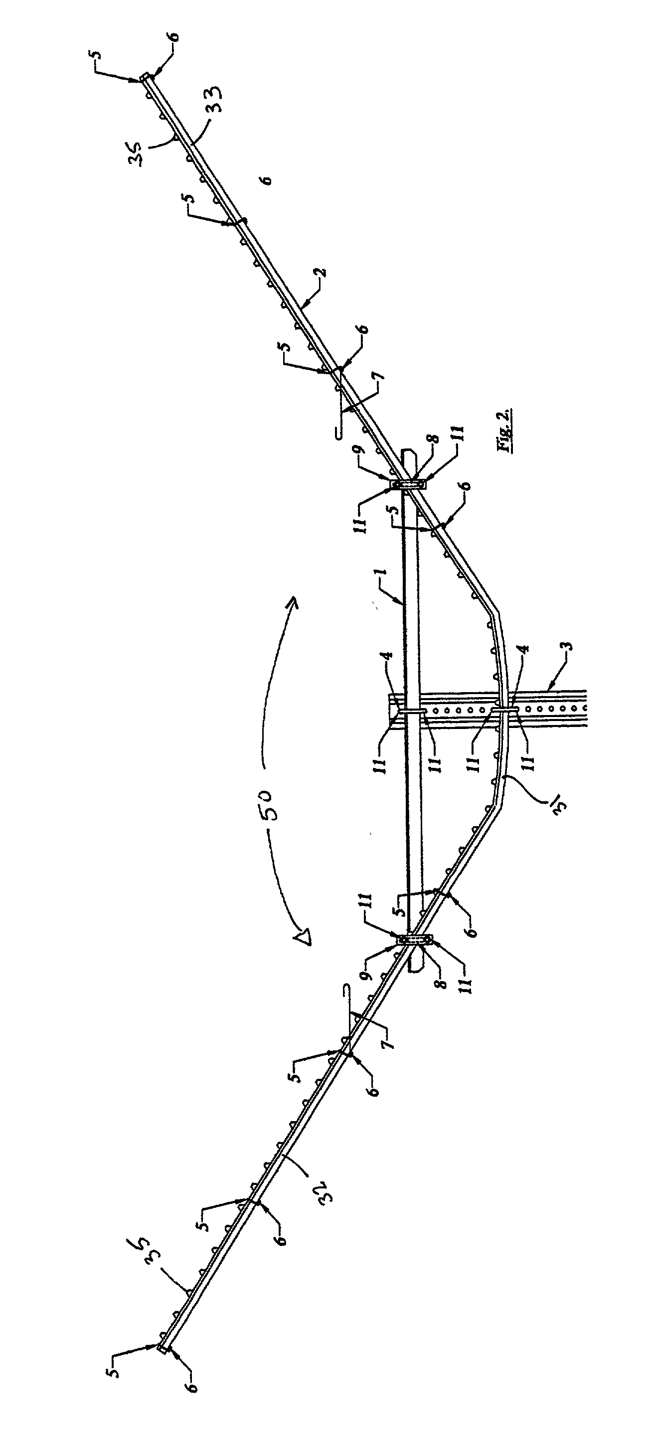
[0052] The trellis structure of the present invention will be described herein with reference to a commercial grape vineyard. However, it is to be understood that the present invention may be used in conjunction with any suitable plant or growing crop.

[0053] Turning now to the drawings, it is seen that the support structure of the present invention is generally indicated by the numerals 1, 2 and 3 in FIGS. 1-4. While the support structure of the present invention is adaptable for use in a wide variety of different environments, it is particularly well suited to large scale commercial farming operations where the commercial crops are grown in rows and require segregation of certain portions thereof in the training, pruning, management and harvesting of the crops before, during and after the growing seasons. One such environment is in management, harvesting and other crop husbandry practices required in the commercial farming of grapevines. The support apparatus of the present inventi...


PUM

PropertyMeasurementUnit
angleaaaaaaaaaa
angleaaaaaaaaaa
angleaaaaaaaaaa

Abstract

A new trellis support structure and a method for its production for use in supporting vine borne crops. The support structure includes a metallic support member that is bent into a modified U-shape and attached to a metallic cross arm using a process that produces consistent results. The combination of the U-shaped member and cross arm is then attached to a vertical support post at two different locations: one attachment at the center of the U-shaped member, and the other attachment at the center of the cross arm in an axial alignment with the support post. The structure is extremely strong, capable of supporting considerable weight, not likely to shift, and less prone to failure from fatigue. The support structure is produced by first bending the central section of a metallic support member into a U-shape, placing the bent member on a specially designed adjustable jig, and attaching a cross arm. This assembly is then attached to a support post in two places preventing pivotal rotation of the combined structure once it is mounted to the support post.

Description

[0001] This application claims the benefit of U.S. provisional application No. 60 / 338,537 filed on Nov. 30, 2001.[0002] 1. Field of the Invention[0003] The present invention relates to structures used to support growing crops, and more particularly to the combination of an improved cross arm and bent trellis support member for use in a trellis structure to support vine borne crops.[0004] 2. Description of the Prior Art[0005] Various trellis structures are widely used in the training and support of commercial crops. A typical commercial agricultural grape vineyard is made up of a plurality of parallel rows of growing plants. In order to train the growth of the plants and to support the plants and the crops they bear, a plurality of upright support structures are typically deployed in parallel in the rows with the plants, the structures supporting a plurality of wires strung from one end of each row to the other. A typical support structure includes a vertical post having one end buri...

Claims


Application Information

Patent Timeline
Patent Type & Authority Applications(United States)
IPC IPC(8): A01G9/12A01G17/06A01G17/14
CPCA01G17/06Y10T29/49904Y10T29/53978Y10T29/49901Y10T29/49908Y10T29/49902Y10T29/49895
Inventor PARRISH, DAVID
Owner A&P STRUCTURES
Why Eureka
Try Eureka