Chip-mounting device and method of alignment

a chip-mounting device and alignment technology, applied in the direction of metal working apparatus, printed circuit manufacture, manufacturing tools, etc., can solve the problems of plurality of alignments, difficulty in controlling the positional shift within the target accuracy range of one alignment, and the error of parallel movement getting out of the target accuracy rang

Inactive Publication Date: 2003-06-12
TORAY ENG CO LTD
View PDF8 Cites 6 Cited by
  • Summary
  • Abstract
  • Description
  • Claims
  • Application Information

AI Technical Summary

Benefits of technology

[0010] Although a table corresponding to a conventional movable table can be used as the above-described coarse adjustment table, in the present invention, the coarse adjustment table has brake means capable of fixing the position of the coarse adjustment table after coarse adjustment. This coarse adjustment table has relatively large control ranges of stroke and rotation similarly to those in a conventional movable table. On the other hand, the fine adjustment means finely adjusts the position so as to further approach the position to a target position after positioning by the coarse adjustment table, and therefore, it may have a small stroke. As such fine adjustment means, for example, means having a piezo element can be employed. By using a piezo element, a fine displacement (a fine expansion or a fine contraction) can be realized with a high accuracy in correspondence with applied voltage, and the position of the chip-holding tool or the substrate-holding stage can be adjusted finely and at a high accuracy by utilizing the fine displacement.
[0011] Further, for the above-described chip-mounting device, a linear scale (for example, a glass linear scale) can be used as means for detecting the adjusted position of a chip or a substrate. In order to realize a further high-accuracy alignment in consideration of the thermal deformation (thermal expansion or thermal shrinkage) of the linear scale, it is preferred that the linear scale is fixed at a predetermined reference position on its central portion in the longitudinal direction and the expansion of the linear scale is allowed in both directions from the reference position. In such a condition, for example, as compared with a case where the linear scale is fixed at its both ends, only the reference position, which is a target position for positioning or a near position, is fixed and a positional shift or a thermal deformation at a position near the reference position is suppressed to be extremely small, and therefore, a positional detection with a higher accuracy becomes possible. By adjusting the position of a chip or a substrate based on the feedback of the higher-accuracy positional detection, it becomes possible to control the position to a target position with a further high accuracy.
[0014] Since the fine adjustment means does not require a large stroke and it is constituted as means only for controlling a fine movement, a high-accuracy fine adjustment, which has not been achieved only by a conventional movable table, may be possible. Besides, because the fine adjustment is carried out at a condition where there is no variation factor in positional control as described above, the position may be adjusted to a target position to be controlled with a high accuracy only by one-time fine adjustment. Namely, in the present invention, positioning with an extremely high accuracy becomes possible by the two-stage control of substantially one-time coarse adjustment and one-time fine adjustment, alignment and chip mounting with submicron level (for example, 0.1 .mu.m), which has not been achieved by a conventional method, becomes possible. Further, because only the two-stage control is required and it is not necessary to repeat alignment at many times as in the conventional method, the target accuracy can be achieved quickly, and the tact time can be greatly shortened.
[0015] Thus, in the present invention, since the fine adjustment is carried out by the fine adjustment means at a condition where the coarsely adjusted position achieved by the coarse adjustment table is fixed, the alignment between a chip and a substrate can be carried out with a high accuracy and quickly, positioning at submicron level, which has not been achieved by a conventional method, becomes possible, and the tact time in the chip mounting can be greatly shortened.

Problems solved by technology

In such a method, because the positional shift between both alignment marks is usually great in the state of the coarse positioning as described above, it is difficult to control the positional shift within a target accuracy by one alignment, and a plurality of alignments are necessary.
However, in such a alignment carrying out the parallel movement and the rotation concurrently, even if an error of the parallel movement has been controlled within a set range in a previous alignment, when a next rotational control is carried out, because there occurs a deflection of a rotational axis (a deflection of .theta. axis), the error of the parallel movement gets out from the range of the target accuracy again, and therefore, sometimes an accuracy higher than the error of the deflection of the axis cannot be achieved.
Moreover, because the number of the repetition times of alignment increases in order to achieve the target accuracy, there is a problem that the tact time becomes long.
Therefore, the controlled position varies by an amount corresponding to this oscillation of .+-.one pulse, there occurs an unavoidable limit in positioning. accuracy, and in practice, positioning at submicron level is difficult.
This coarse positioning corresponds to a first alignment among alignment operations carried out repeatedly in a conventional method, and the time required for this alignment may be relatively short.

Method used


Image

  • Chip-mounting device and method of alignment
  • Chip-mounting device and method of alignment
  • Chip-mounting device and method of alignment

Examples


Embodiment Construction

[0020] Hereinafter, desirable embodiments of the present invention will be explained referring to figures.

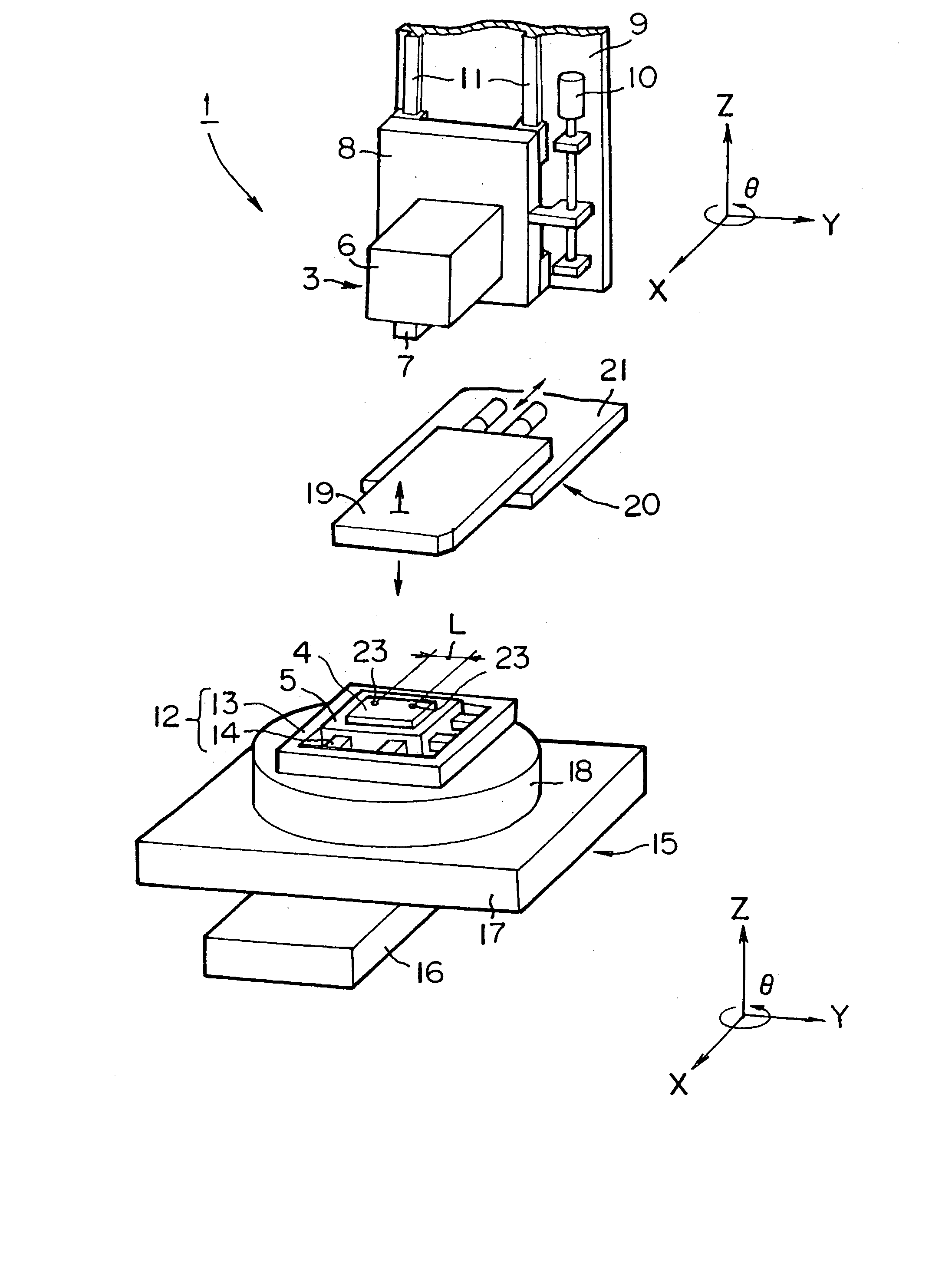
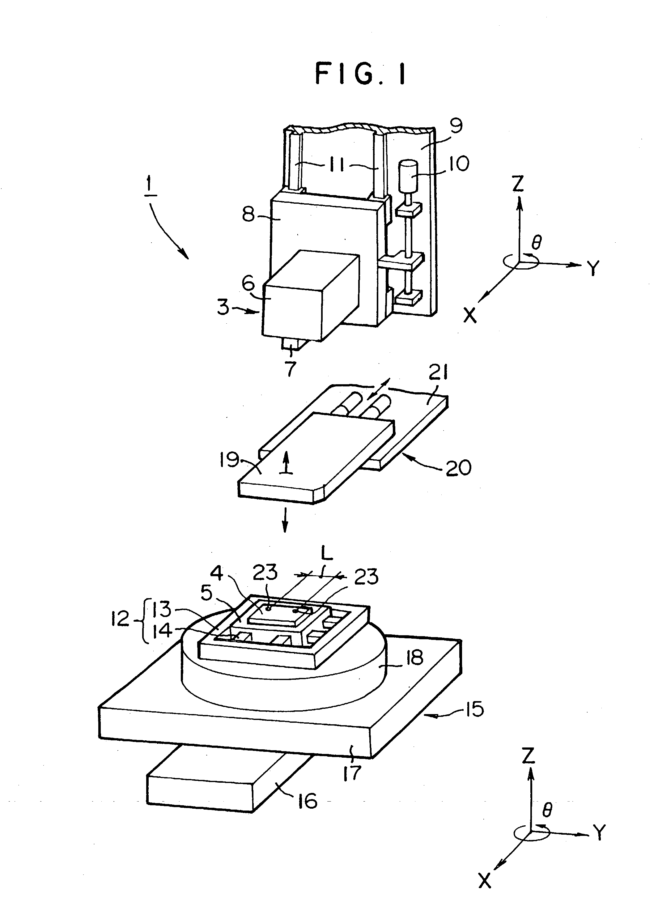
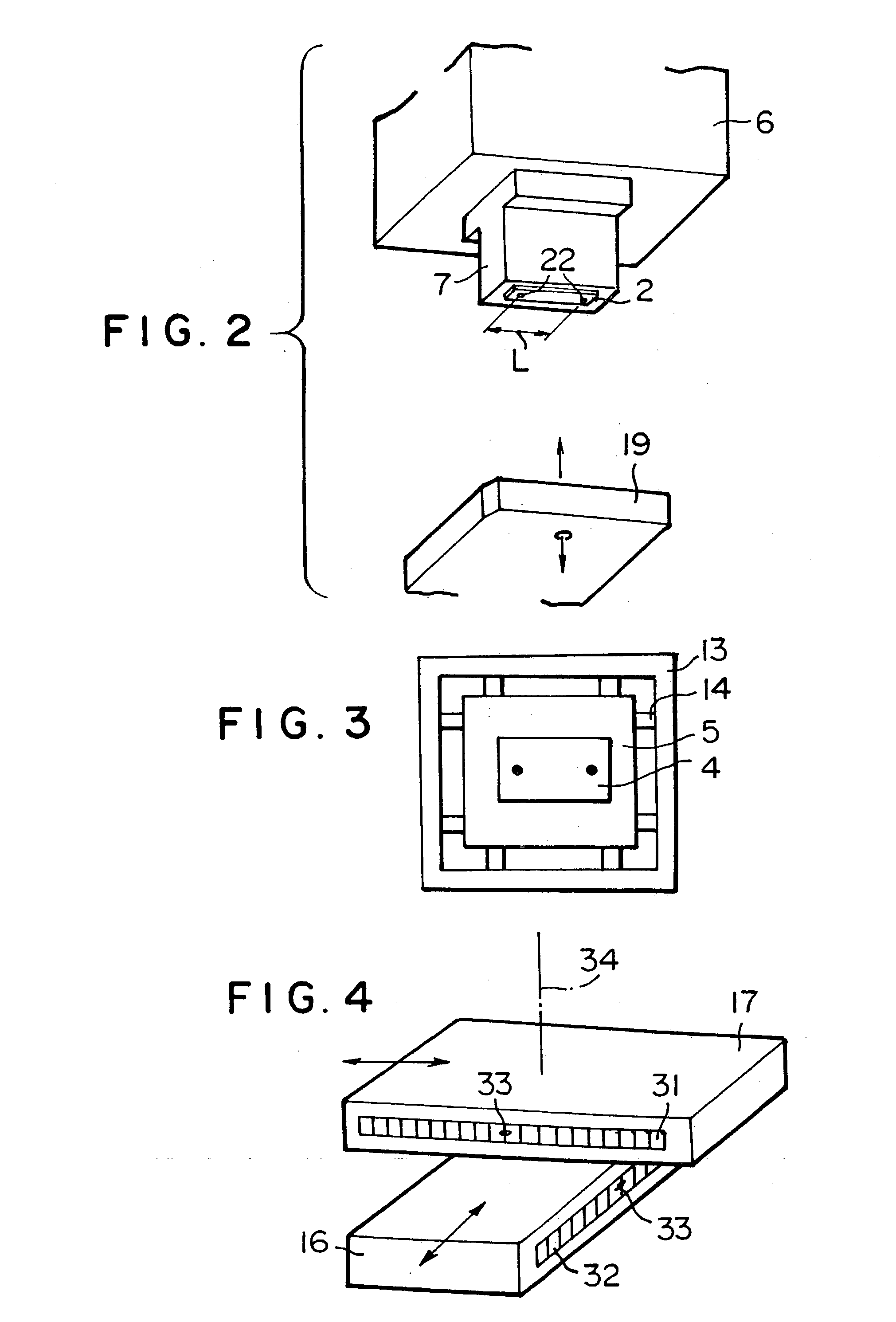
[0021] FIGS. 1-3 show a chip-mounting device according to an embodiment of the present invention. In FIGS. 1 and 2, chip-mounting device 1 has a head 3 for holding a chip 2 (for example, a semiconductor chip) by suction, etc. and a substrate-holding stage 5 disposed below the head 3 for holding a substrate 4 such as a circuit board or a liquid crystal panel by suction, etc. Head 3 has a block 6 and a chip-holding tool 7 provided on the lower end of the block 6 (hereinafter, also referred to as merely "tool").

[0022] Head 3 is fixed to a movable table 8, and the movable table 8 is controlled to be moved up and down in the direction of Z axis along a pair of vertical rails 11 fixed to an upper frame 9 by drive control of a servo motor 10 attached to the upper frame 9. Positioning between chip 2 and substrate 4 can be carried out, for example, so that only the control of moving up a...


PUM


Abstract

A chip-mounting device comprises a chip-holding tool and a substrate-holding stage. At least one of the chip-holding tool and the substrate-holding stage is placed on a coarse adjustment table for coarse positioning of a chip or a substrate. Brake means for fixing the positioned coarse adjustment table is provided on the coarse adjustment table. Fine adjustment means for fine positioning of a chip or a substrate is provided on the coarse adjustment table. The chip-mounting device allows alignment with submicorn accuracy to be performed quickly, shortening tact time in chip mounting remarkably.

Description

[0001] The present invention relates to a chip-mounting device and a method of alignment in the chip-mounting device, and specifically to a chip-mounting device and a method of alignment in the device in which a desired alignment can be carried out with a high accuracy and quickly.BACKGROUND ART OF THE INVENTION[0002] As known well, in a chip-mounting device, the position of a chip (for example, a semiconductor chip) held on a chip-holding tool and the position of a substrate (for example, a liquid crystal panel) held on a substrate-holding stage disposed below the chip-holding tool are positioned precisely, and in the positioned state, chip mounting is carried out by moving the chip-holding tool down.[0003] For example, prior to the chip mounting, either the chip-holding tool or the substrate-holding stage is moved for coarse positioning between the chip and the substrate, and thereafter, for example, predetermined alignment marks provided on the chip and the substrate are recogniz...

Claims


Application Information

Patent Timeline
IPC IPC(8): H05K13/04
CPCH05K13/0413Y10T29/49133Y10T29/49131Y10T29/53174H01L24/75H01L2924/14H05K13/0812H01L2924/00H01L21/60
Inventor ARAI, YOSHIYUKIYAMAUCHI, AKIRAKAWAKAMI, MIKIO
Owner TORAY ENG CO LTD
Why Eureka
Try Eureka