
Architectural moldings for protecting, concealing and accessing indoor wiring and cables

a technology for protecting, concealing and accessing indoor wiring and cables, applied in the direction of connection contact material, connection device connection, building components, etc., can solve the problems of unable to pre-wire new "smart" homes and buildings, and not being able to fully anticipate future needs and opportunities

Inactive Publication Date: 2003-06-12
SEAMANS JAMES D +2
View PDF6 Cites 25 Cited by
  • Summary
  • Abstract
  • Description
  • Claims
  • Application Information

AI Technical Summary

Benefits of technology

The solution allows for faster, easier installation and modification of electrical systems, reduces installation time and costs, and provides an aesthetically pleasing appearance that complements the structure, while maintaining the integrity of the wall and allowing for future renovations.

Problems solved by technology

Most existing homes were not built to accommodate these new technologies.
Furthermore, the current rate of change in these technologies makes it very difficult to pre-wire new "smart" homes and buildings to fully anticipate future needs and opportunities.
The star topography requires an increasing number of wires and cables in greater lengths, compounding the difficulty of accommodating the new technologies.
Existing finished structures, in particular, present difficulties to installing such systems or networks due to the complications of running wiring and cables in the interior of walls that have already been covered.
However, running wiring and cables horizontally through the studs is difficult, time-consuming, and disruptive to the finished structure.
The drilling of holes or notching of studs can weaken the structure.
The demolition and repair procedure is often much more costly and time-consuming than the actual running of cables.
The installer risks running into existing electrical power lines, plumbing lines, or other obstructions concealed within the walls, ceilings, and floors.
Exterior walls and shared walls between adjacent dwelling spaces can make installing these additional wires and cables nearly impossible due to the presence of fiberglass or foam weather insulation, sound insulation, or fire walls.
Surface-mounted wiring raceways and conduits with snap-on covers have been designed for carrying electrical wires, but their use detracts from the appearance of a residence or professional office.
Generally, they are considered undesirable for residences because they look like wire raceways rather than finished interior trim that complements the appearance of a home.
Furthermore, baseboard-style raceways do not provide means for continuing wiring and cables around doors, windows, or other wall openings to reach any point in the room or to connect these same wires and cables back to a central control hub.
However, to date, millwork has not been designed to provide a channel for electrical wiring and cables that can extend completely around the perimeter of rooms via baseboard, casings, crown moldings and related connection moldings.
Further, ordinary millwork cannot provide easy access for installation and modification of the wiring, cables, and related electrical devices via removable portions of the molding.
Performing these steps on the moldings after installation is time-consuming and inefficient compared to painting or staining prior to installation, due to non-ergonomic working positions and the care required to avoid getting finish treatments on adjacent surfaces.
Since standard means of installing moldings does not permit it to be easily removed, subsequent maintenance or remodeling (such as painting, stripping, staining, wallpapering, changing flooring, etc.) requires a relatively high degree of care to perform these steps on the moldings and / or adjacent surfaces.

Method used


Image

  • Architectural moldings for protecting, concealing and accessing indoor wiring and cables
  • Architectural moldings for protecting, concealing and accessing indoor wiring and cables
  • Architectural moldings for protecting, concealing and accessing indoor wiring and cables

Examples


Embodiment Construction

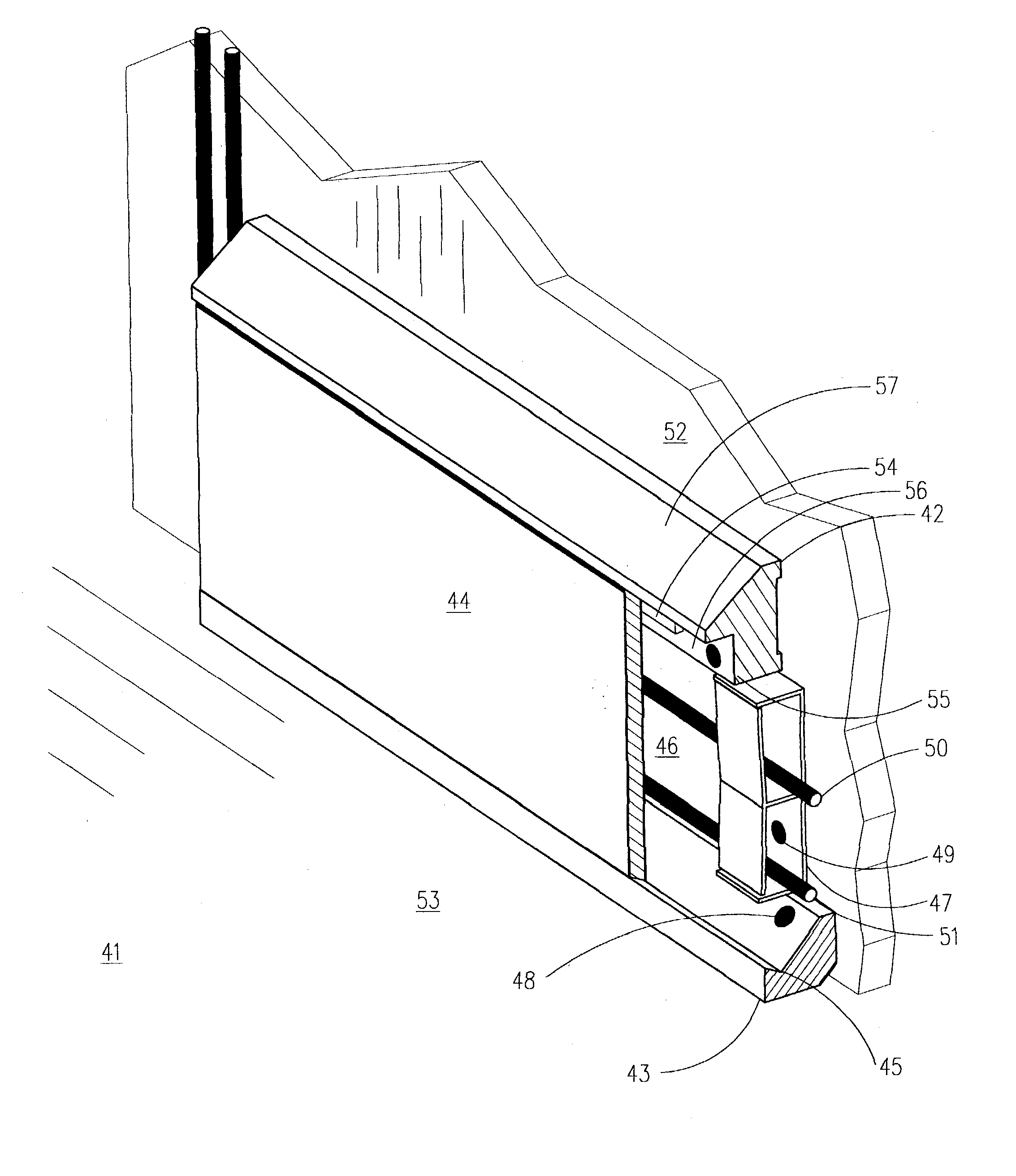
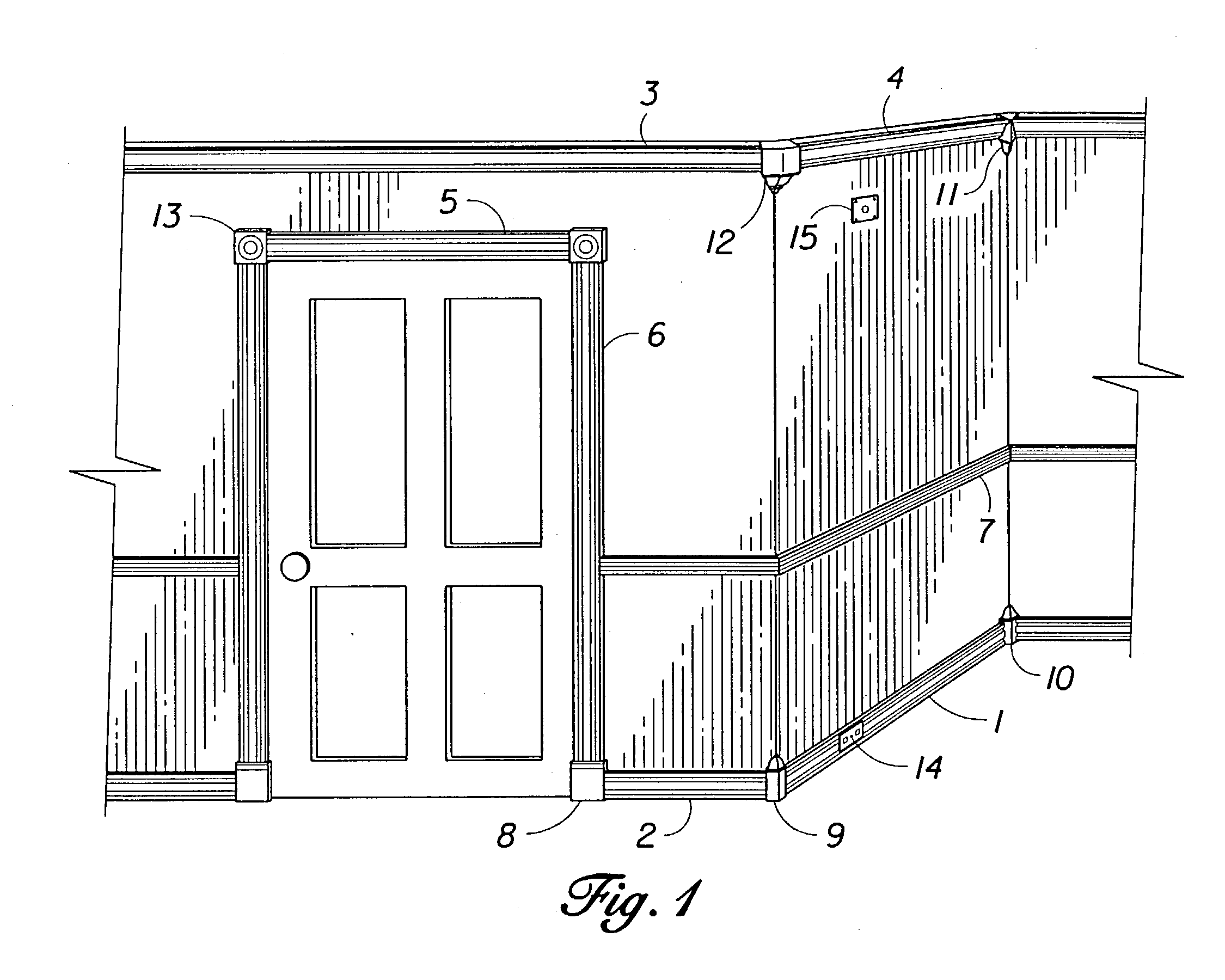
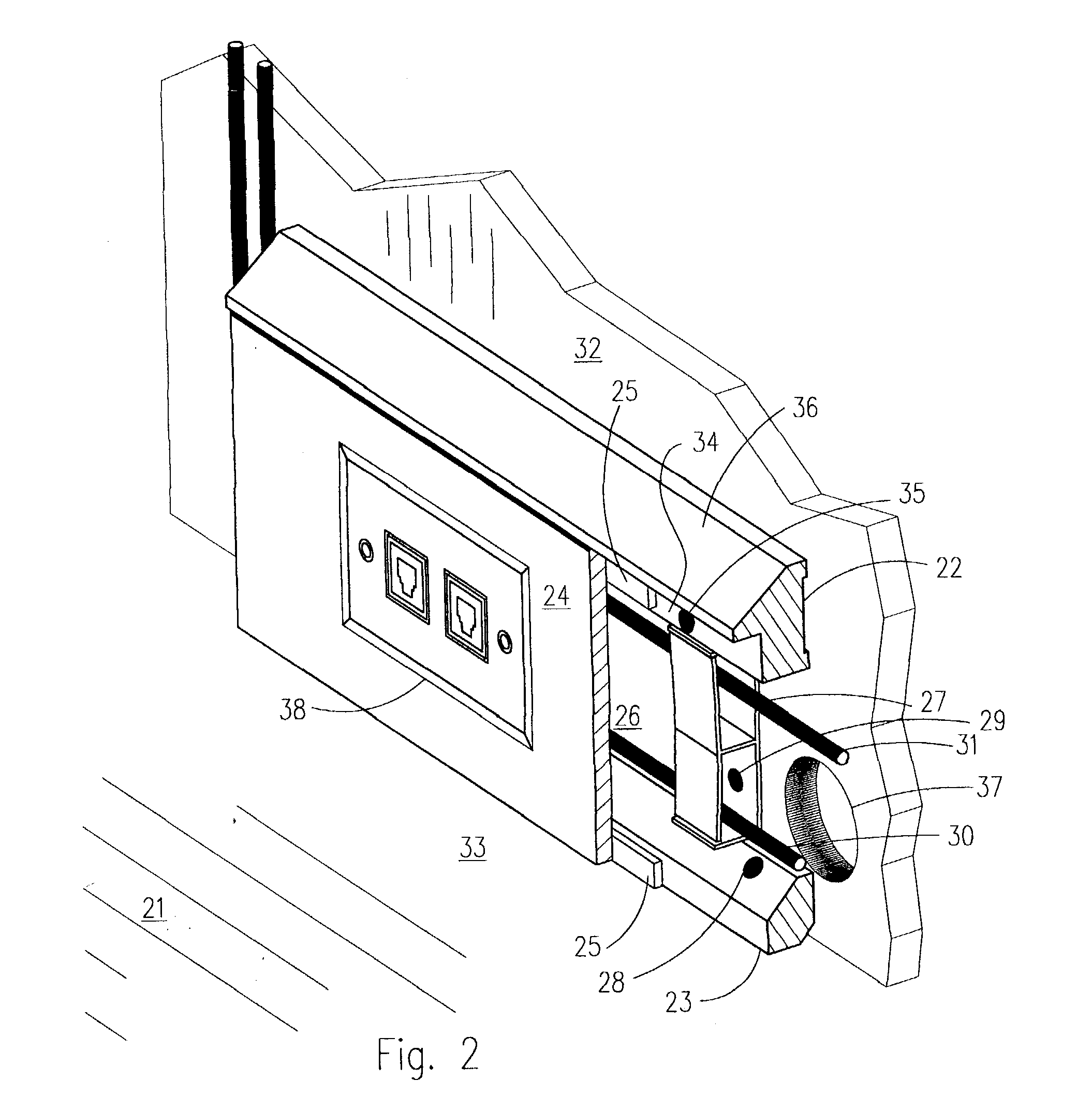
[0043] In accordance with the present invention, FIG. 1 shows interior walls and a door in a home with a system of decorative moldings of the present invention covering the low-voltage wiring and cables. Baseboard moldings 1, 2 have the appearance of decorative baseboard, but also provide channels or conduits for wiring and cables. Crown moldings 3, 4 are also designed to cover wiring and cables along the upper part of a room. Casing moldings 5, 6 around a doorway provide channels or conduits for home automation or networking cables and wiring; they are particularly useful for extending the electrical connections around doors and windows of rooms and throughout homes. Chair rail 7, an alternative decorative molding, provides a channel or conduit for connecting circuits and networks at a height a few feet above floor level. Plinth block 8 is an example of a millwork piece installed at the intersection of the baseboard 2 and the door casing 6. Each such piece has openings on the side ...


PUM


Abstract

A system of architectural moldings that form a passage for electrical wiring (30), coaxial cables, fiber optic cables, and associated devices used in transmitting low-voltage power, communication, and control signals. The architectural moldings may also be used to cover pre-existing wiring raceways and conduits. The system may be installed when constructing a building or when retrofitting an existing structure. The moldings can be removably mounted on the interior surfaces of residential and commercial structures in a manner that allows for easy removal and replacement of some or all of the moldings without disturbing the enclosed wiring and cables or harming finished surfaces. The moldings may be made of wood, polyurethane, fiberboard, or any material suitable for manufacturing pieces that resemble baseboards, cornice moldings, chair rails, casings, or other interior millwork. The system of moldings facilitates upgrades or modifications to the number, type, or placement of wiring, cables, outlets, jacks, or associated devices.

Description

[0001] 1. Field of the Invention[0002] This application is a continuation in part of application Ser. No. 09 / 836,022, which was filed on Apr. 17, 2001, and which issued as U.S. Pat. No. ______. This invention relates to coverings or enclosures for electrical wiring and cables. More particularly, it relates to novel and improved protective architectural moldings that provide channels for electrical wiring, cables, and associated devices. Sections of the moldings may be easily removed and reinstalled to facilitate initial installation and modifications to the electrical wiring and cables used for automation, communication, control, entertainment, networking, and / or security systems.[0003] 2. Description of the Prior Art[0004] Recent years have brought unprecedented advancement in communication, entertainment, computer networking, security, automation, and control systems for homes and commercial buildings. Most existing homes were not built to accommodate these new technologies. Furth...

Claims


Application Information

Patent Timeline
Patent Type & Authority Applications(United States)
IPC IPC(8): H02G3/00H02G3/04H02G3/30
CPCH02G3/266
Inventor SEAMANS, JAMES D.SEAMANS, WILLIAM J.SEAMANS, DAVID L.
Owner SEAMANS JAMES D
Learn More