Vehicle mounted bearing assembly

Inactive Publication Date: 2003-06-19
NTN CORP
View PDF4 Cites 47 Cited by
  • Summary
  • Abstract
  • Description
  • Claims
  • Application Information

AI Technical Summary

Problems solved by technology

Accordingly, it has often been observed that some of the electric lines forming the electric wiring, including those of the signal transmitting cable are damaged or broken upon collision with gravel stones or rocks or under the influence of freeze-up of a tire house.
According to the above mentioned publication, it has been found involving a problem in that since the detected rotation signal outputted form the rotation detecting sensor is in the form of an analog signal, the detected rotation signal is susceptible to external noises.
However, the site where the wheel support bearing a

Method used


Image

  • Vehicle mounted bearing assembly
  • Vehicle mounted bearing assembly
  • Vehicle mounted bearing assembly

Examples


Example

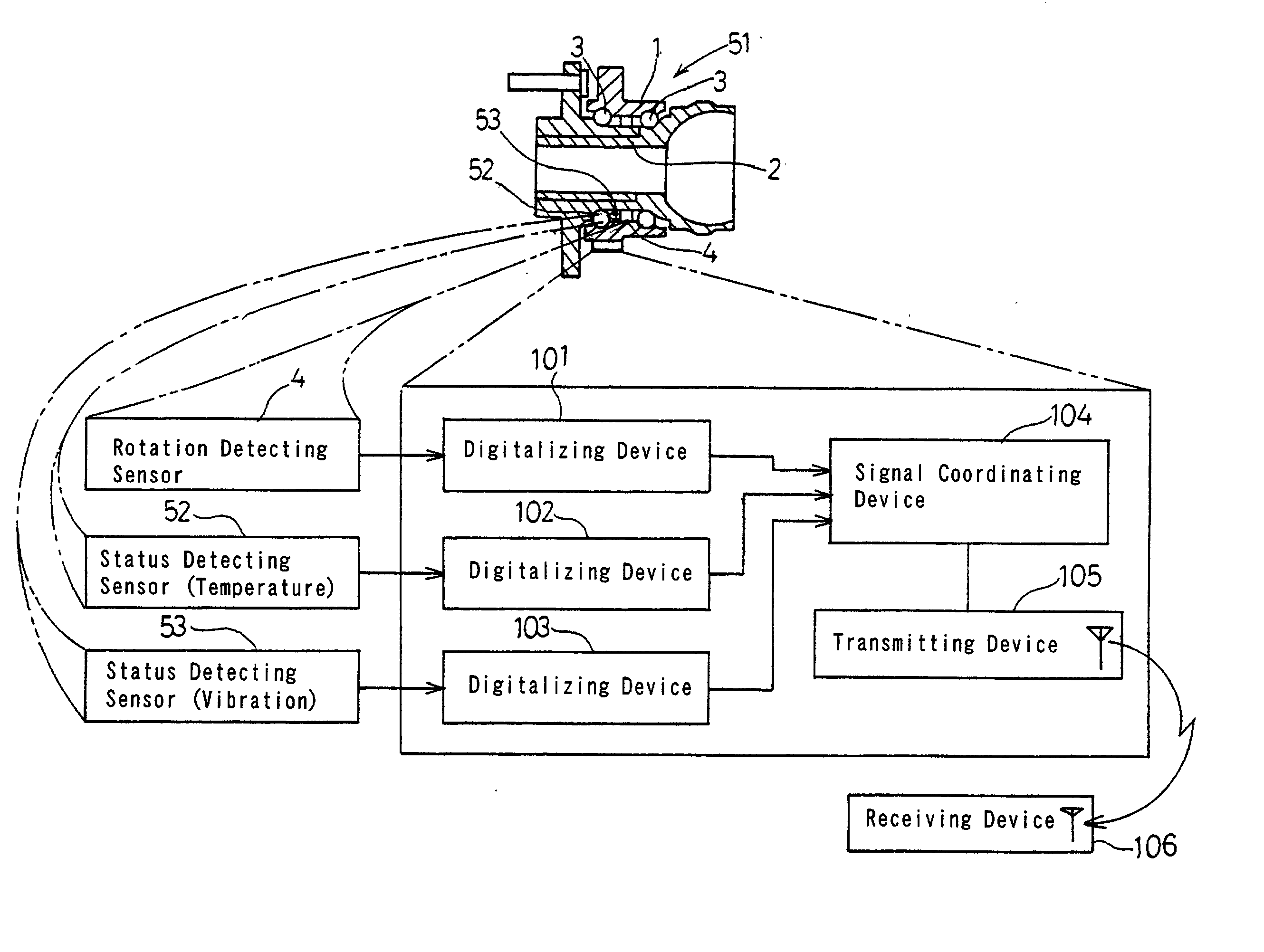
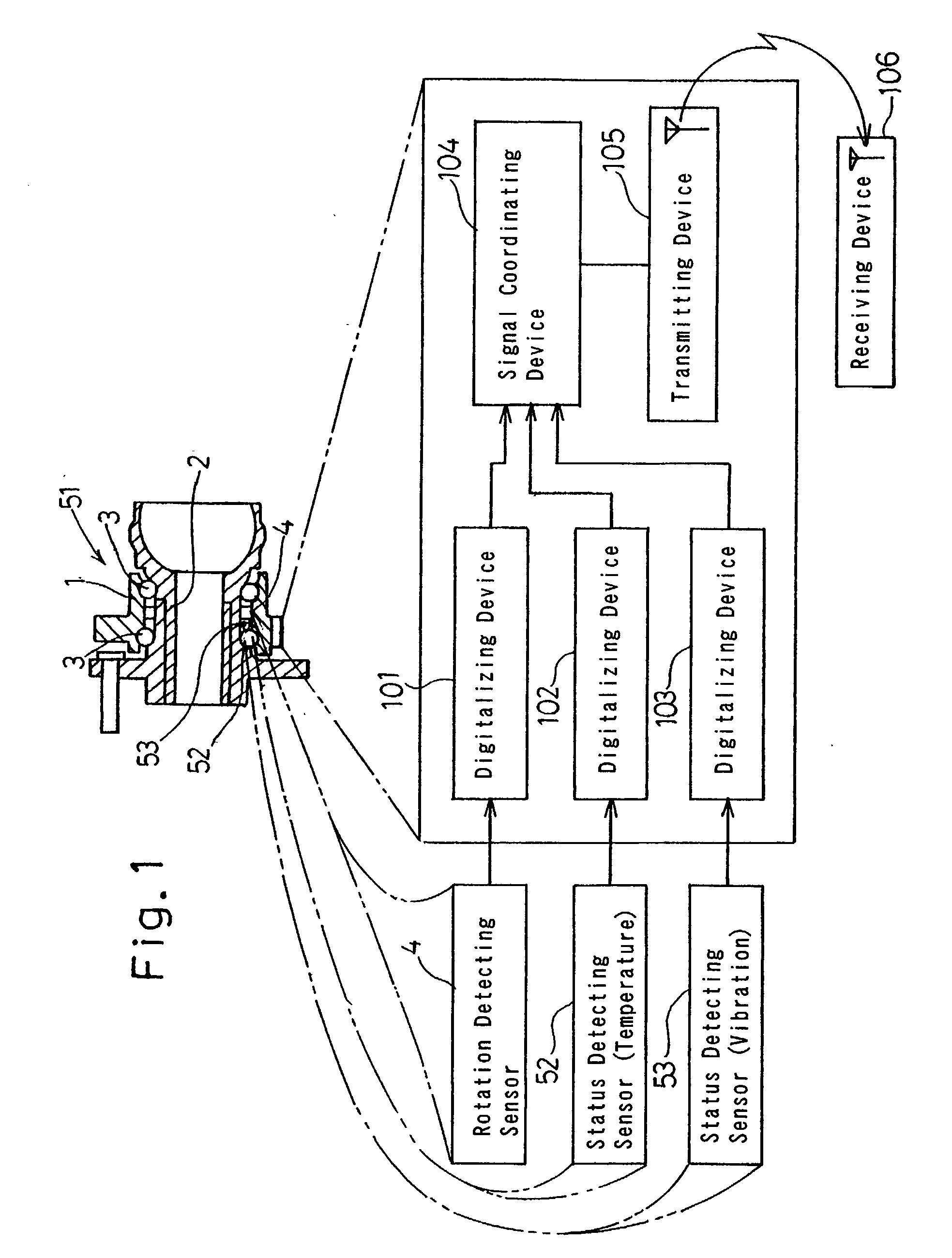
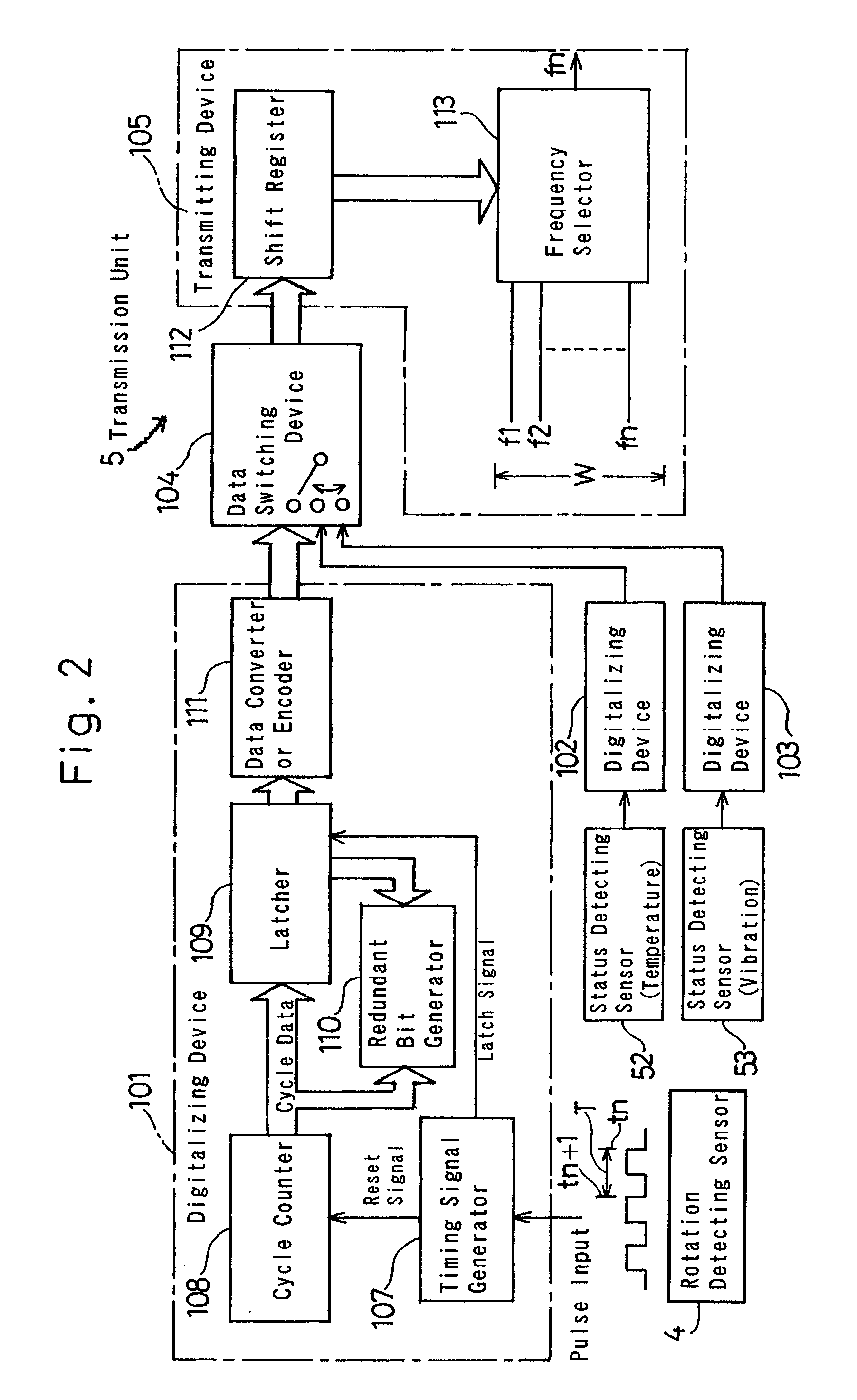
[0110] The vehicle mounted bearing assembly according to the second embodiment of the present invention shown in FIG. 9A is an inner race rotating type of a third generation and is used as a wheel support bearing assembly for the support of the drive axle. The rotation detecting sensor 4 used therein is the thrust type.

Example

[0111] The outer member 1 has the vehicle body fitting flange 1a which is, as is the case with the first embodiment, is fitted to the wheel bearing support component 12a such as a knuckle of the automobile body structure 12. The inner member 2 includes the hub wheel 2A, and a separate inner race forming member 2C mounted on an outer periphery of the end of the hub wheel 2A. The hub wheel 2A has the wheel mounting flange 2a formed integrally therewith. The raceways 8 and 9 on the inner member 2 are formed on the hub wheel 2A and the inner race forming member 2C, respectively.

[0112] The inner member 2 is coupled with the outer race 15a of the constant velocity universal joint 15 that is manufactured separate from the vehicle mounted bearing assembly. The outer race 15a of the constant velocity universal joint 15 has a hollow axle 16 formed integrally therewith so as to extend from an outer bottom portion thereof, which hollow axle 16 is inserted into an inner peripheral surface of the...

Example

[0126] FIG. 11 illustrates a third embodiment of the present invention. The vehicle mounted bearing assembly shown therein is a vehicle mounted bearing assembly of a second generation inner race rotating type, wherein the rotation detecting sensor 4 defining a rotation sensor is a thrust type. In this embodiment, the vehicle body fitting flange la referred to hereinbefore in connection with the foregoing embodiments is formed integrally with the outer member 1.

[0127] FIG. 12 illustrates a fourth preferred embodiment of the present invention. The vehicle mounted bearing assembly shown therein is a vehicle mounted bearing assembly of a third generation inner race rotating type and is used for rotatably supporting the drive axle. In this embodiment, one open end of the annular space between the inner and outer members 1 and 2 of the bearing assembly, where the sealing member 11 is disposed, is provided with a reduced diameter portion 81 defined in a portion of the outer periphery of th...


PUM


Abstract

To enhance a detecting capability for monitoring a bearing assembly and also to minimize complication of the structure resulting from increase in functionality, a vehicle mounted bearing assembly 51 includes inner and outer members 2 and 1 with rows of rolling elements 3 operatively interposed between the inner and outer members 2 and 1, and a rotation detecting sensor 4. A sensor output from the rotation detecting sensor 4 is digitalized by a digitalizing unit 101 and is subsequently transmitted wireless by a transmitting unit 105. One or both of status detecting sensors 52, 53 for detecting different statuses of the bearing assembly 51 other than rotation such as temperature and vibration occurring in the bearing assembly 51 may be additionally employed. A signal coordinating unit 104 may also be used for coordinating the respective sensor outputs from the rotation detecting sensor and the status detecting sensors to enable those sensor outputs to be transmitted wireless by the transmitting unit 105.

Description

[0001] 1. Field of the Invention[0002] The present invention generally relates to a vehicle mounted bearing assembly such as a wheel support bearing assembly for supporting a wheel of an automotive vehicle and, more particularly, to the vehicle mounted bearing assembly of a type that is equipped with a rotation detecting sensor used as a component part of an automobile anti-lock control system.[0003] 2. Description of the Prior Art[0004] In an automobile anti-lock braking system or the like, the necessity has long been recognized to detect the number of revolutions or rotational speed of one or more vehicle wheels so that the behavior of the vehicle wheels tending to skid can be controlled. A rotation detecting sensor employed in an automotive vehicle for this purpose is generally incorporated in a wheel support bearing assembly that is used to support a vehicle wheel. A detected rotation signal outputted from the rotation detecting sensor that is indicative of the rotational speed ...

Claims


Application Information

Patent Timeline
IPC IPC(8): B60B27/00F16C19/52F16C33/58F16C33/78G01P3/44
CPCB60B27/00F16C41/004F16C41/007F16C2326/02G01P3/443F16C19/52F16C33/7896F16C41/008F16C19/186F16C19/187F16C33/7886F16C33/58
Inventor OKADA, KOICHI
Owner NTN CORP
Why Eureka
Try Eureka