
Solar energy converter and solar energy conversion system

a solar energy and converter technology, applied in the direction of generator/motor, light radiation electric generator etc., can solve the problems of poor practicality, bad energy conversion efficiency, and inability to guarantee that the use of thermal power generation, hydroelectric power generation and nuclear power generation will provide a stable supply of electricity

Inactive Publication Date: 2003-06-19
AKAMATSU NORIO +1
View PDF0 Cites 22 Cited by
  • Summary
  • Abstract
  • Description
  • Claims
  • Application Information

AI Technical Summary

Benefits of technology

[0075] Specifically, cost reduction and easy assembling can be achieved due to disuse of a sunlight reflection member.

Problems solved by technology

However, there is no guarantee that the use of thermal power generation, hydroelectric power generation and nuclear power generation will provide a stable supply of electricity in the long run as a method of generating electric energy, due to the exhaustion of the resources and limited amount of supply.
Moreover, in conventional photovoltaic batteries, the energy conversion efficiency is bad and not practical since the sunlight which can be used by the solar cell is only a part of the spectra of light currently emitted from the sun.
Therefore, the cost-performance does not reach a level of practical use.
The material is not a special one with limited availability or a high production cost.

Method used


Image

  • Solar energy converter and solar energy conversion system
  • Solar energy converter and solar energy conversion system
  • Solar energy converter and solar energy conversion system

Examples


first embodiment

[0094] First Embodiment

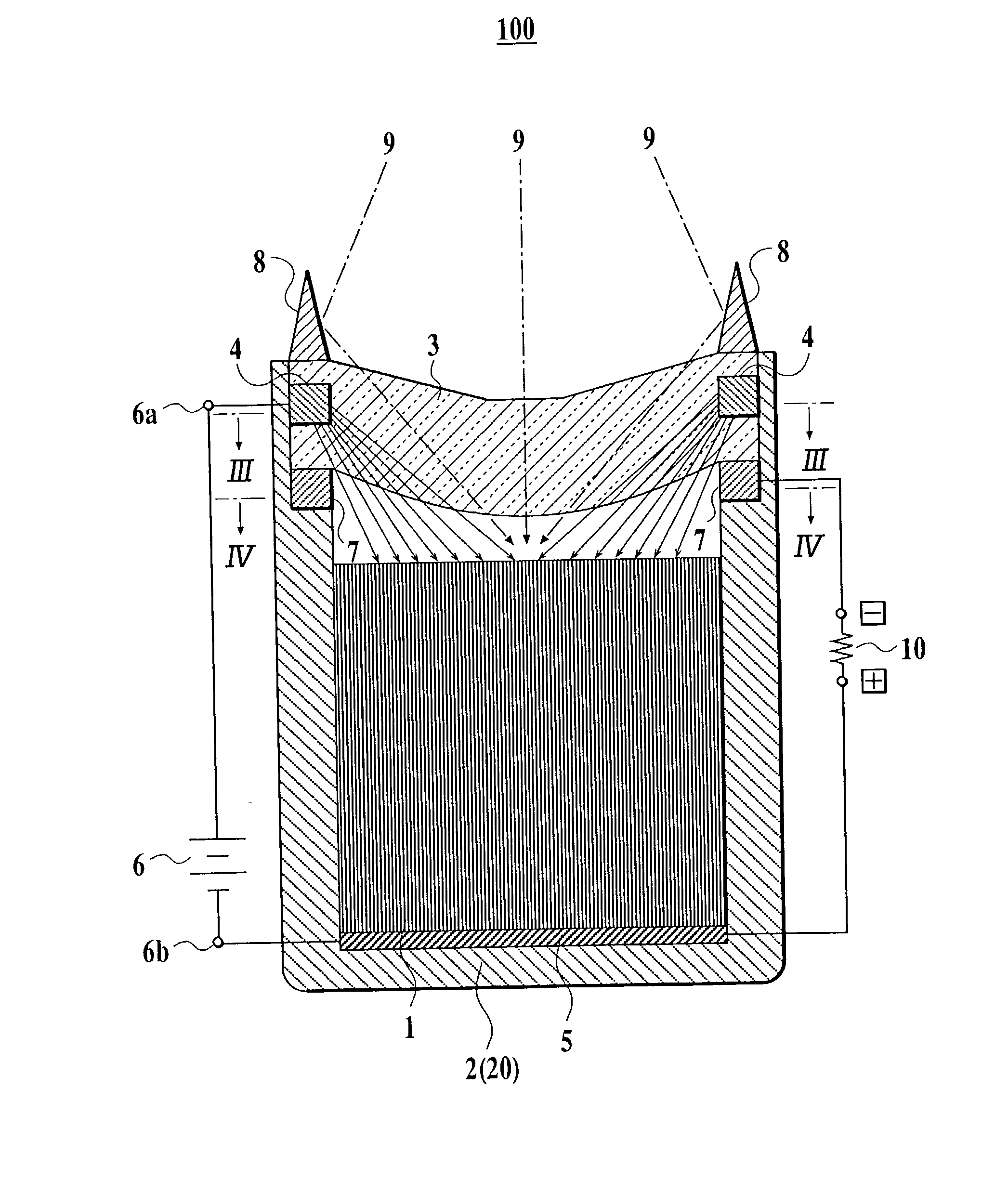
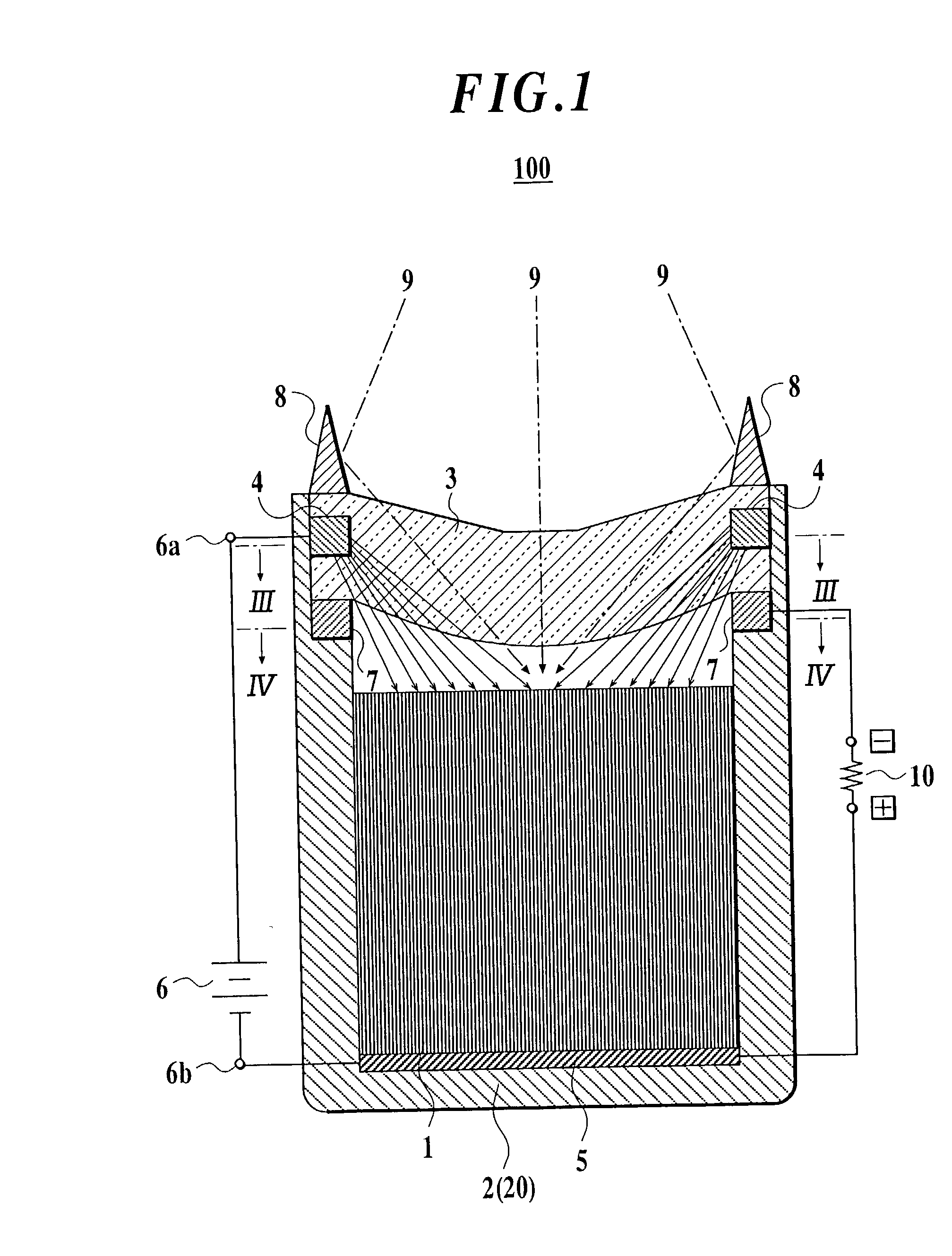
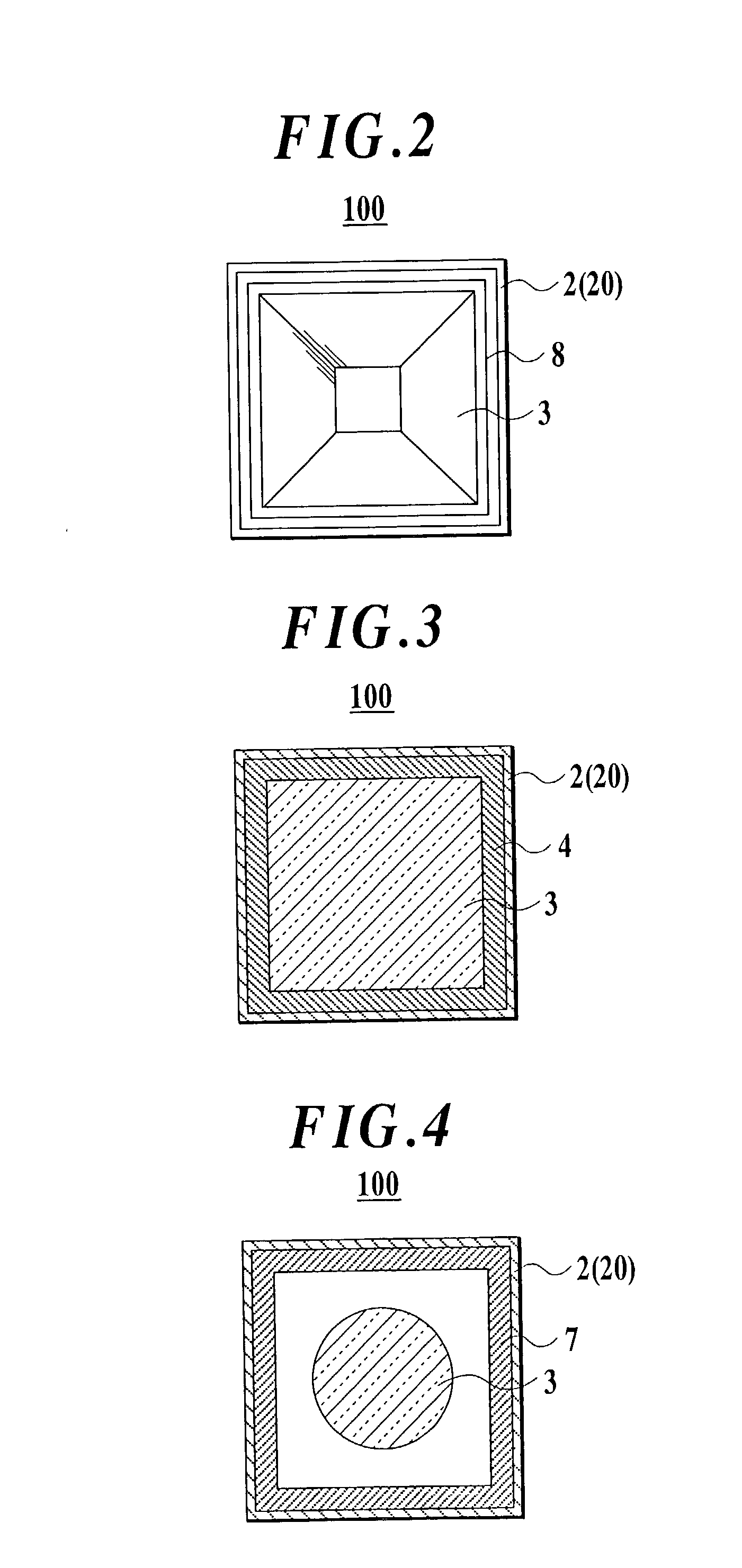
[0095] FIG. 1 is a cross-sectional side view showing a solar energy converter according to the first embodiment of the present invention. FIG. 2 is a plane view showing the solar energy converter according to the first embodiment of the present invention.

[0096] As shown in FIGS. 1 and 2, the solar energy converter 100 comprises an insulated vacuum vessel 2 containing an electron emitter 1 therein. A light-concentrating instrument 3 made of insulated material that is pervious to light, is attached to the upper portion of the vacuum vessel 2. An electron accelerator 4 is provided within a light-concentrating instrument 3. A cathode 5 is provided at the bottom of a vacuum vessel 2, and is electrically connected with the electron emitter 1. The electron accelerator 4 and the cathode 5 are connected with an electric field supplier 6.

[0097] An electron collector 7 is provided in the vacuum vessel 2 positioned below the electric accelerator 4, while coming into conta...

second embodiment

[0122] Second Embodiment

[0123] FIG. 6 shows a solar energy converter according to the second embodiment of the invention. In the figure, the same reference numerals are attached to the same parts of the second embodiment of the invention as the first embodiment, and only different parts are explained below.

[0124] In the solar energy converter 200 according to the embodiment of the invention, the electron emitter 1 comprises diamond. The diamond used in the solar energy converter is constructed in such a manner that ions are implanted into a flat plate-shaped diamond so as to form nanoscale projections and cavities on its surface. This is for the purpose of improving the electron emission characteristics. By using such an electron emitter 1, the same working effect as the first embodiment can be obtained.

third embodiment

[0125] Third Embodiment

[0126] FIG. 7 shows a solar energy converter according to the third embodiment of the invention. In the figure, the same reference numerals are attached to the same parts of the third embodiment of the invention as the first embodiment, and only different parts are explained below.

[0127] In the solar energy converter 300 according to this embodiment of the invention, the electron accelerator 4a is coated with, for example, aluminum or the like to perform the role of a sunlight reflection member. The electron accelerator 4a is so constructed as to let the sunlight which irradiates on it, and the sunlight 9 directed to the electron collector 7, reflect in the direction of the electron emitter 1. This is for the purpose of increasing the sunlight 9 concentration efficiency.

[0128] When the sunlight reflection member 8 is provided on the upper surface of the light-concentrating instrument 3, that is, provided outside of the light-concentrating instrument 3, the fun...


PUM


Abstract

A solar energy converter includes: a light-concentrating instrument; an electron emitter in an insulated vacuum vessel, emitting electrons in a vacuum as a temperature rises by sunlight; an electron accelerator within the light-concentrating instrument; a cathode on a surface of the electron emitter opposite to a surface which is irradiated by sunlight, and electrically connected with the electron emitter; an electric field supplier having a positive terminal and a negative terminal; and an electron collector in the vacuum vessel, collecting the emitted electrons flying from the electron emitter toward the electron accelerator; wherein the electron accelerator is connected with the positive terminal and the cathode is connected with the negative terminal to generate an electric field, and the electron collector is used as a negative generator electrode and the cathode is used as a positive generator electrode in which the collected electrons migrate to the electron emitter to generate electricity.

Description

[0001] 1.Field of the Invention[0002] The present invention relates to a solar energy converter that converts solar energy emitted from the sun into electric energy and a solar energy conversion system.[0003] 2. Description of Related Art[0004] Conventionally, the energy from sources such as thermal power, hydroelectric power and nuclear power, for example, an electric generation system like a rotating electric generator in which conductors are rotated in a magnetic field to force electrons to migrate to generate electricity has been employed so far. Moreover, photovoltaic batteries, comprising semiconductors and widely known as a method of converting solar energy, attracted attention as clean electric energy.[0005] However, there is no guarantee that the use of thermal power generation, hydroelectric power generation and nuclear power generation will provide a stable supply of electricity in the long run as a method of generating electric energy, due to the exhaustion of the resour...

Claims


Application Information

Patent Timeline
Patent Type & Authority Applications(United States)
IPC IPC(8): H01J31/00F24J2/00H01L31/00H02NH02N3/00H02N6/00
CPCF24J2/07H02S99/00Y02E10/41H01J45/00F24S20/20Y02E10/50Y02E10/40H02S10/00
Inventor AKAMATSU, NORIO
Owner AKAMATSU NORIO
Learn More