
Air Conditioning System

a technology of air conditioner and air conditioner coil, which is applied in the field of air conditioner systems, can solve the problems of reducing requiring significant space and energy. it can improve the efficiency and performance of the unit, improve the humidity control, and reduce the energy consumption of the condenser coil

Inactive Publication Date: 2003-06-19
COLUMBUS HEATING & VENTILATING
View PDF0 Cites 14 Cited by
  • Summary
  • Abstract
  • Description
  • Claims
  • Application Information

AI Technical Summary

Benefits of technology

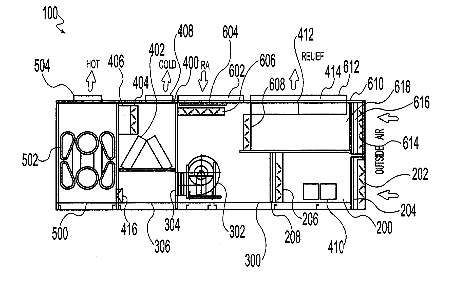
[0010] These and other limitations of the prior art are overcome by the present invention which provides a self-contained, fully-integrated, energy efficient heating and cooling system or apparatus for conditioning the air on the interior of a building. This heating and cooling system includes all of the benefits of the constant volume system while providing improved humidity control without the additional energy required to reheat cooled air. Unlike commercially available prior art systems that typically locate the condensing coil on the exterior of a building, the present invention locates the condenser coil within the housing of the unit itself so that conditioned air returned to the unit can be used to reduced the energy consumption of the condenser coil. Additionally, a secondary heating apparatus, separate and distinct from the main heat exchanger, is included with the present invention to provide tempered air in certain situations. Finally, the present invention optionally includes a secondary heat exchanger or energy reclaiming device that further enhances the efficiency and performance of the unit.
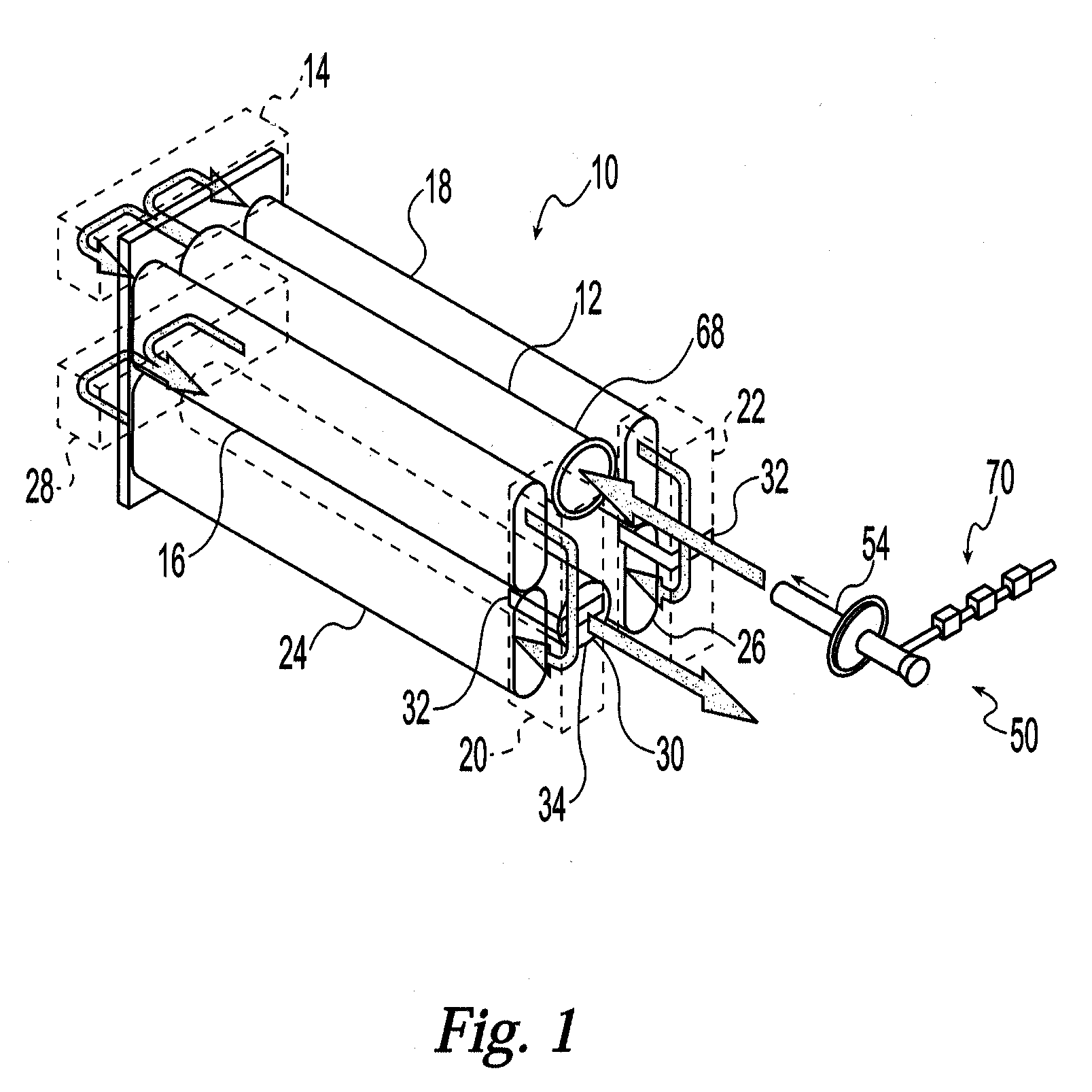
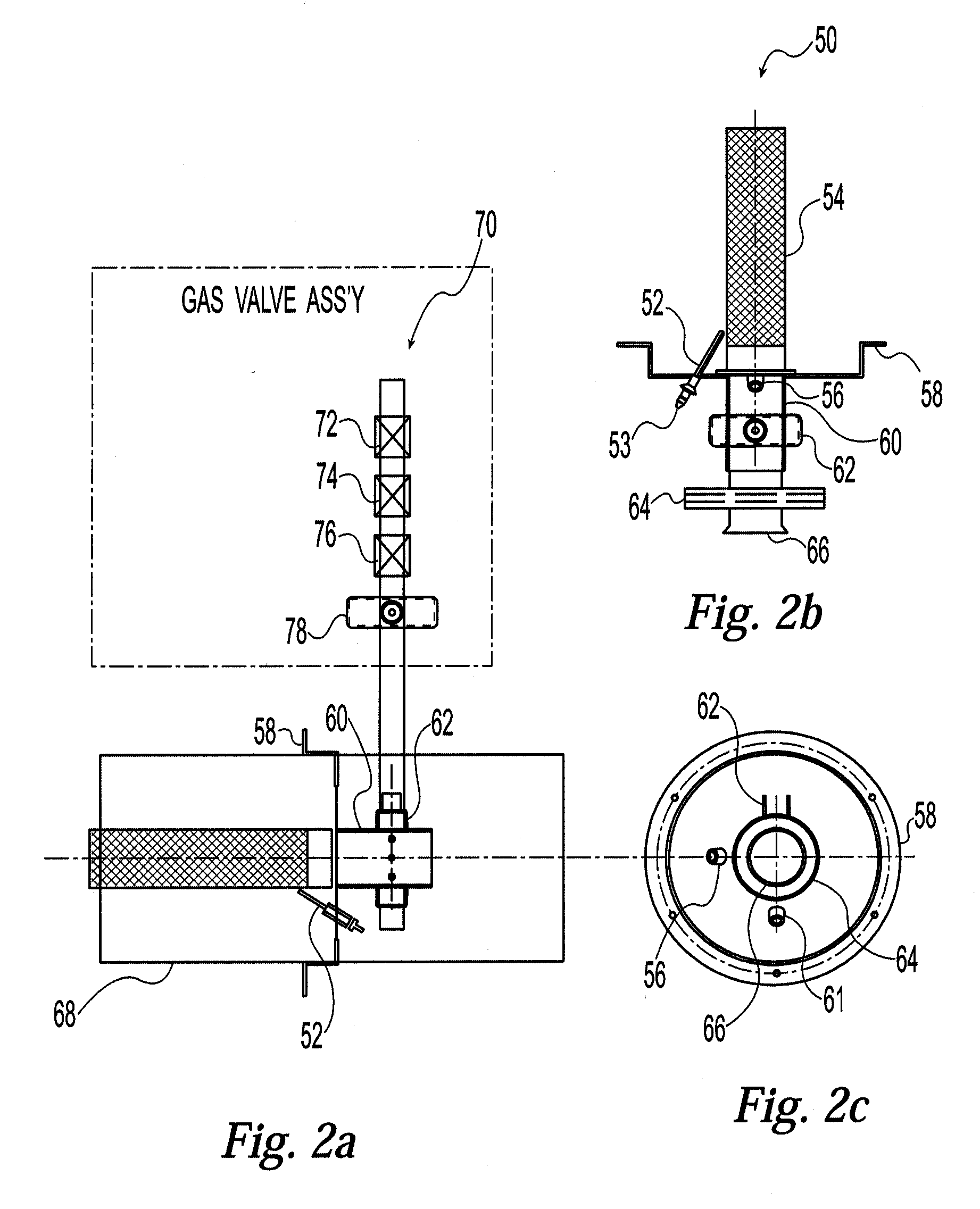
[0011] An exemplary embodiment of this invention includes a means for creating airflow through the apparatus, a section for cooling the airflow, a section for heating the airflow, means for directing the airflow into the cooling section or into the heating section, a reheat device for tempering (i.e., reheating) the airflow exiting the cooling section, a return air section for receiving air returned to the apparatus from the building interior, and means for pulling the returned air out of the return air section and venting the returned air to the environment outside of the building.The heating section of the present invention also provides a novel four-pass heat exchanger a "four-pass" heat exchanger which may be manufactured from sections of cast iron or other suitable materials, and a high efficiency combustion burner which may be integrated into the four-pass heat exchanger. Advantages of this invention include improved efficiency, reduced size, and enhanced performance of the heat exchanger / burner assembly. An automated system for operating dual duct heating and cooling systems which utilize the heat exchanger / burner assembly of the present invention is also provided.

Problems solved by technology

Such air conditioners are often very large in size and require significant amounts of space and energy to effectively handle and condition the air inside such industrial or commercial buildings.
Despite these advantages, constant volume systems are problematic in that they redirect air from the cooling section to the heating section of the unit.
This redirection of air results in the final air supply being delivered to the room without the dehumidifying benefit of the system"s cooling coil.
The heat generated by the coil is vented to the outside environment and any energy present in the form of heat is lost to the environment.
Such heat exchangers are often very large in size and consequently may be impractical for some applications.
Additionally, these heat exchangers cannot typically be adapted to different system requirements and configurations.
Furthermore, if the heat exchanger cracks or fractures, the entire unit must often be replaced.

Method used


Image

  • Air Conditioning System
  • Air Conditioning System
  • Air Conditioning System

Examples


Embodiment Construction

[0023] The present invention provides a self-contained, fully-integrated heating and cooling system, apparatus, or unit for conditioning the air on the interior of a building or group of buildings. An exemplary embodiment of this apparatus includes a means for creating airflow through the apparatus, a section for cooling the airflow, a section for heating the airflow, a means for directing the airflow into the cooling section or into the heating section, a reheat device for tempering the airflow exiting the cooling section, a return air section for receiving air returned to the apparatus from the building interior, and a means for pulling the returned air out of the return air section and venting the returned air to the environment outside of the building.

[0024] In the exemplary embodiment, the reheat device is positioned between the cooling section and the heating section, and a portion of the cooled air exiting the cooling section is directed through the reheat device and is rehea...


PUM


Abstract

Abstract of Disclosure A self-contained, fully-integrated, energy efficient heating and cooling system or apparatus for conditioning the air on the interior of a building which includes a means for creating airflow through the apparatus, a section for cooling the airflow, a section for heating the airflow, a means for directing the airflow into the cooling section or into the heating section, a reheat device for tempering (i.e., reheating) the airflow exiting the cooling section, a return air section for receiving air returned to the apparatus from the building interior, and a means for pulling the returned air out of the return air section and venting the returned air to the environment outside of the building. The heating section of the present invention also provides a four-pass heat exchanger which may be assembled from sections of cast iron or other suitable materials, and a high efficiency combustion burner which may be integrated into the four-pass heat exchanger.

Description

Cross Reference to Related Applications[0001] This application claims the benefit of U.S. Provisional Application No. 60 / 340,621 filed on December 13, 2001 entitled Heat Exchanger and Burner the disclosure of which is incorporated as if fully rewritten herein.Background of Invention[0002] This application claims the benefit of U.S. Provisional Application No. 60 / 340,621 filed on December 13, 2001 entitled Heat Exchanger and Burner the disclosure of which is incorporated as if fully rewritten herein.[0003] Air conditioning or air handling units that include both heating and cooling capabilities are commonplace in modern society. Powerful industrial or commercial air conditioning systems are often utilized to condition (i.e., control the temperature and humidity) the air on the inside of buildings such as office towers, warehouses, factories, and schools. Such air conditioners are often very large in size and require significant amounts of space and energy to effectively handle and co...

Claims


Application Information

Patent Timeline
Patent Type & Authority Applications(United States)
IPC IPC(8): F24F3/052F24F12/00F24F3/044
CPCF24F3/0525Y02B30/16F24F2203/104F24F2012/007F24F3/044F24F12/006Y02B30/563Y02B30/56
Inventor EDWARDS, ROGER, GENE
Owner COLUMBUS HEATING & VENTILATING
Learn More