
Method for enhanced wireless signal distribution

a wireless signal and wireless technology, applied in the direction of network planning, network traffic/resource management, electrical equipment, etc., can solve the problems of duplicate equipment, affecting the reliability of wireless communication, and often not meeting the expectations of indoor environments

Inactive Publication Date: 2003-06-19
MILLS DONALD CHARLES
View PDF4 Cites 74 Cited by
  • Summary
  • Abstract
  • Description
  • Claims
  • Application Information

AI Technical Summary

Benefits of technology

[0026] (c) to eliminate the need for human intervention in re-allocating wireless resources among covered regions; and

Problems solved by technology

However, this expectation is often not met in indoor environments or in areas with difficult (e.g., hilly or heavily forested) terrain.
Many buildings also have significant underground space, providing further impediments to reliable wireless communication.
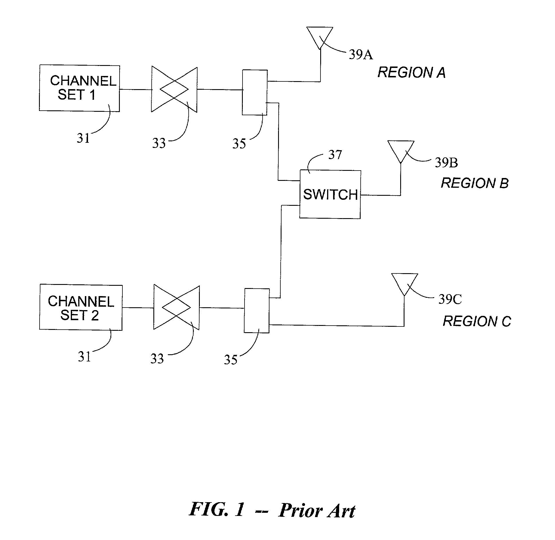
This requires duplicate equipment in the associated base stations and complex switching logic in the base station and / or its switching controller.
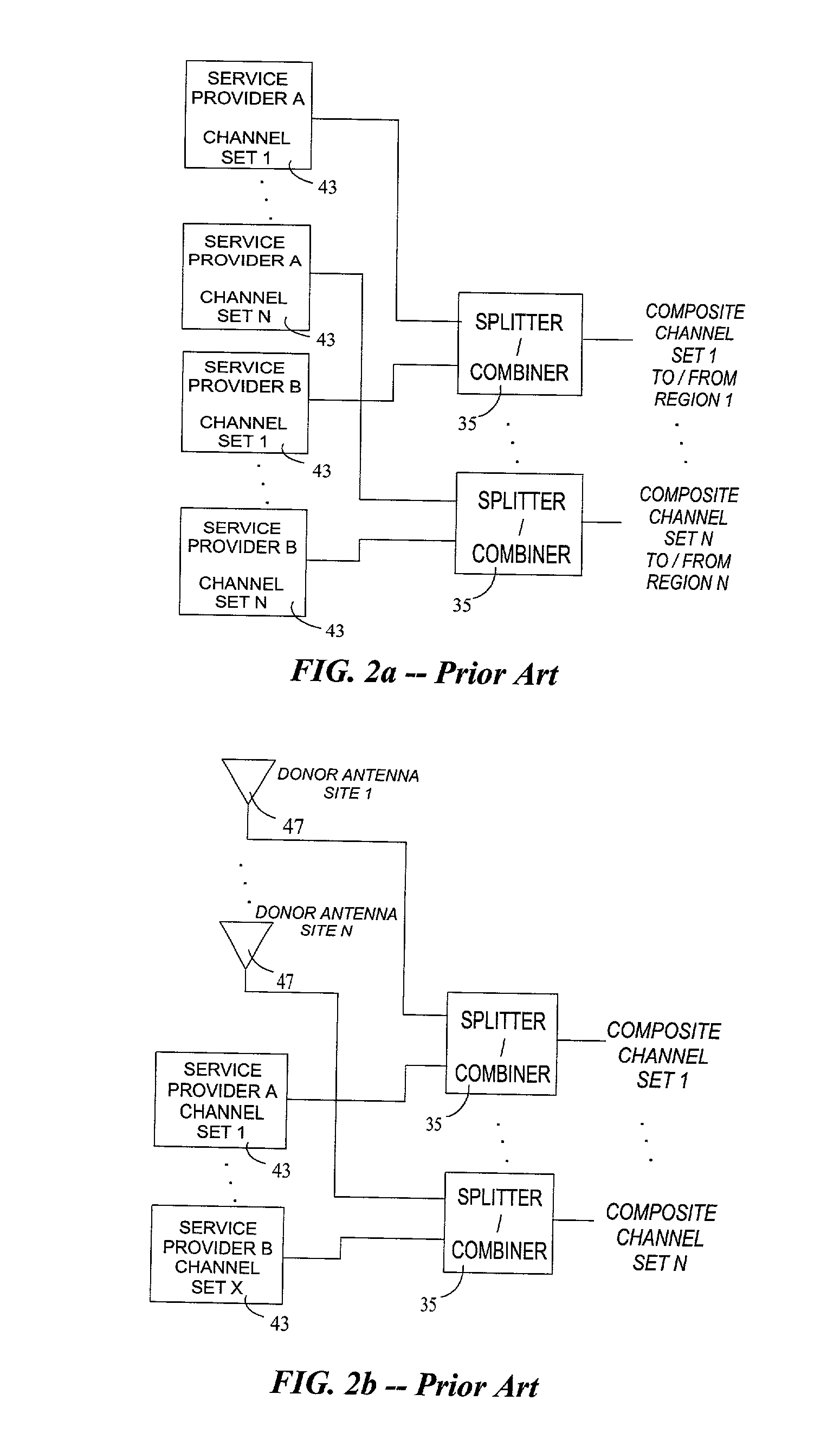
Such an interface is not available if a donor antenna is used.
Though more precise than the other methods, this will seldom be available in such a system, and the complexity in implementing it for multiple service providers employing multiple technologies and equipment from multiple vendors is considerable.

Method used


Image

  • Method for enhanced wireless signal distribution
  • Method for enhanced wireless signal distribution
  • Method for enhanced wireless signal distribution

Examples


Embodiment Construction

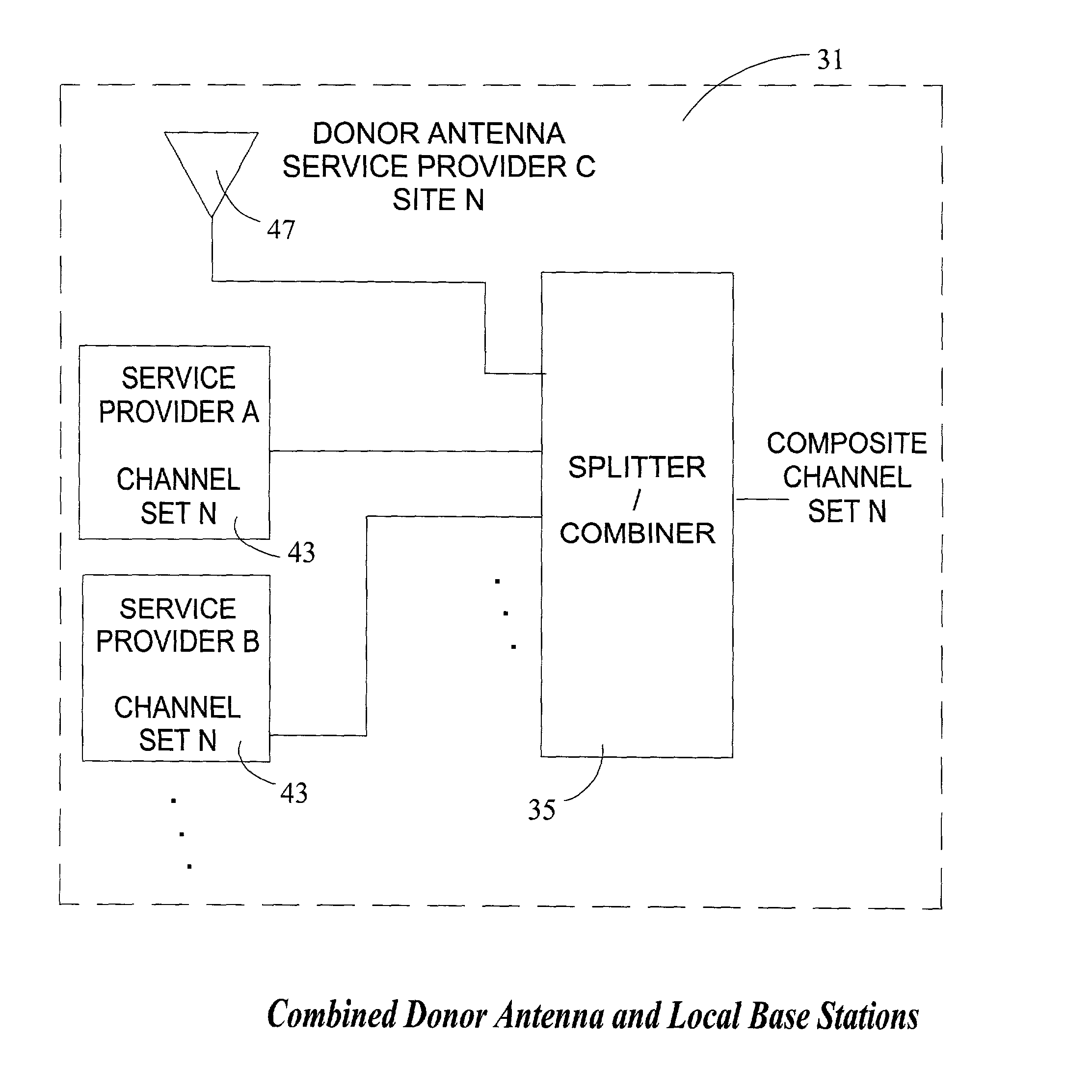
[0036] A preferred embodiment of the present invention is illustrated in FIG. 3. Each radio set 31 is applied to splitter / combiner 35. One output of each splitter / combiner is connected directly to serving antennas 39A and 39C, each serving a region of the confined space. The other output of each splitter / combiner 35 is connected to a monitor / control unit 49. The output of monitor / control unit 49 is connected to serving antenna 39B, which serves subscribers within its region of the confined space. In a donor-site system, fixed regions A 39a and B 38b may not exist; the entire confined space may be switched to the least heavily loaded macro-site.

[0037] The components of the monitoring / logic unit are shown in FIG. 4. Power detectors 51 monitor the radio frequency levels of their respective radio frequency channel sets. Power detectors 51 respond to radio frequency energy in the downlink (base station to subscriber handset) frequency band. The outputs of power detectors 51 are compared ...


PUM


Abstract

Subscriber traffic loading in wireless channel sets (31) is indirectly estimated, and distribution of channel sets (31) among regions (39) in the confined space is optimized to more evenly allocate subscribers among those channel sets (31). Multiple service providers, multiple wireless technologies, and both donor-site and in-building micro-cell implementations are supported.

Description

[0001] Not applicable.[0002] 1. Field of the Invention[0003] This invention relates to a system to increase wireless network capacity within an enclosed area or structure.[0004] 2. Description of Prior Art[0005] As wireless communications has become increasingly commonplace, it has become for many users their preferred method of personal communication. Networks to support wireless communications, particularly "Cellular" and "Personal Communications Systems" or PCS are designed to provide service over a wide geographic area using various techniques to re-use the available spectrum within the system coverage area to support as many users as possible with an acceptable level of service quality.[0006] Digital techniques have been widely deployed to increase capacity, to enable new user services, and to provide improved service quality. In many areas, service providers have deployed multiple digital formats. In North America, for example, wireless service is widely available employing di...

Claims


Application Information

Patent Timeline
Patent Type & Authority Applications(United States)
IPC IPC(8): H04W16/06H04W88/08
CPCH04W16/06H04W24/00H04W88/085H04W72/04H04W28/16
Inventor MILLS, DONALD CHARLES
Owner MILLS DONALD CHARLES
Learn More