

Ballast with lamp sensor and method therefor
a technology of electronic ballast and lamp sensor, which is applied in the field of electronic ballast, can solve the problems of lamp filling, lamp overheating and failure of the switch device commonly found in the electronic ballast circuit, and the lamp may become deactivated, so as to minimize the possibility of components overheating or failing, and the cost is low
- Summary
- Abstract
- Description
- Claims
- Application Information
AI Technical Summary
Benefits of technology
Problems solved by technology
Method used
Image

Examples
Embodiment Construction
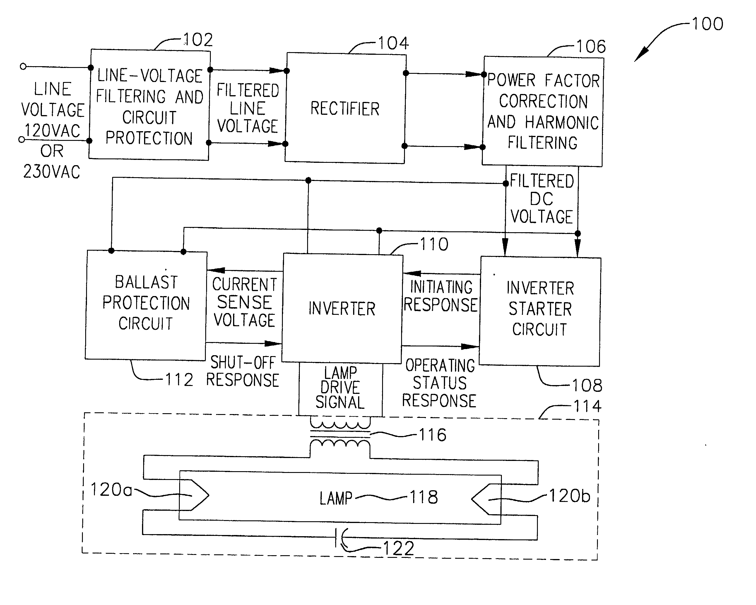
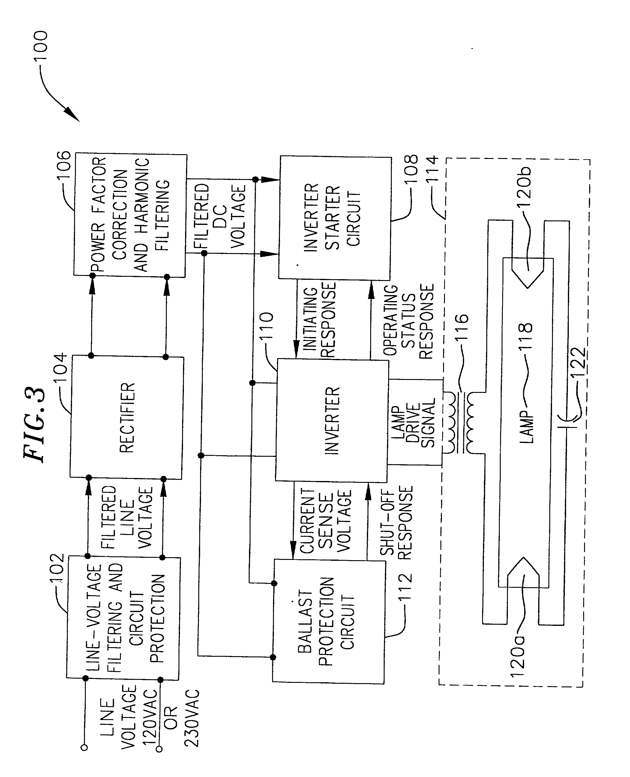
[0021] Fluorescent lamps are used in many applications for providing lighting for commercial buildings, houses, warehouses, parking lots and other applications. One particular application of interest to the invention is the illumination of refrigeration systems. A fluorescent lamp driving circuit, typically termed a ballast, is usually employed in conjunction with the lamp to provide it a lamp drive current for causing the lamp to start illuminating, and to keep the lamp illuminated during normal operations.
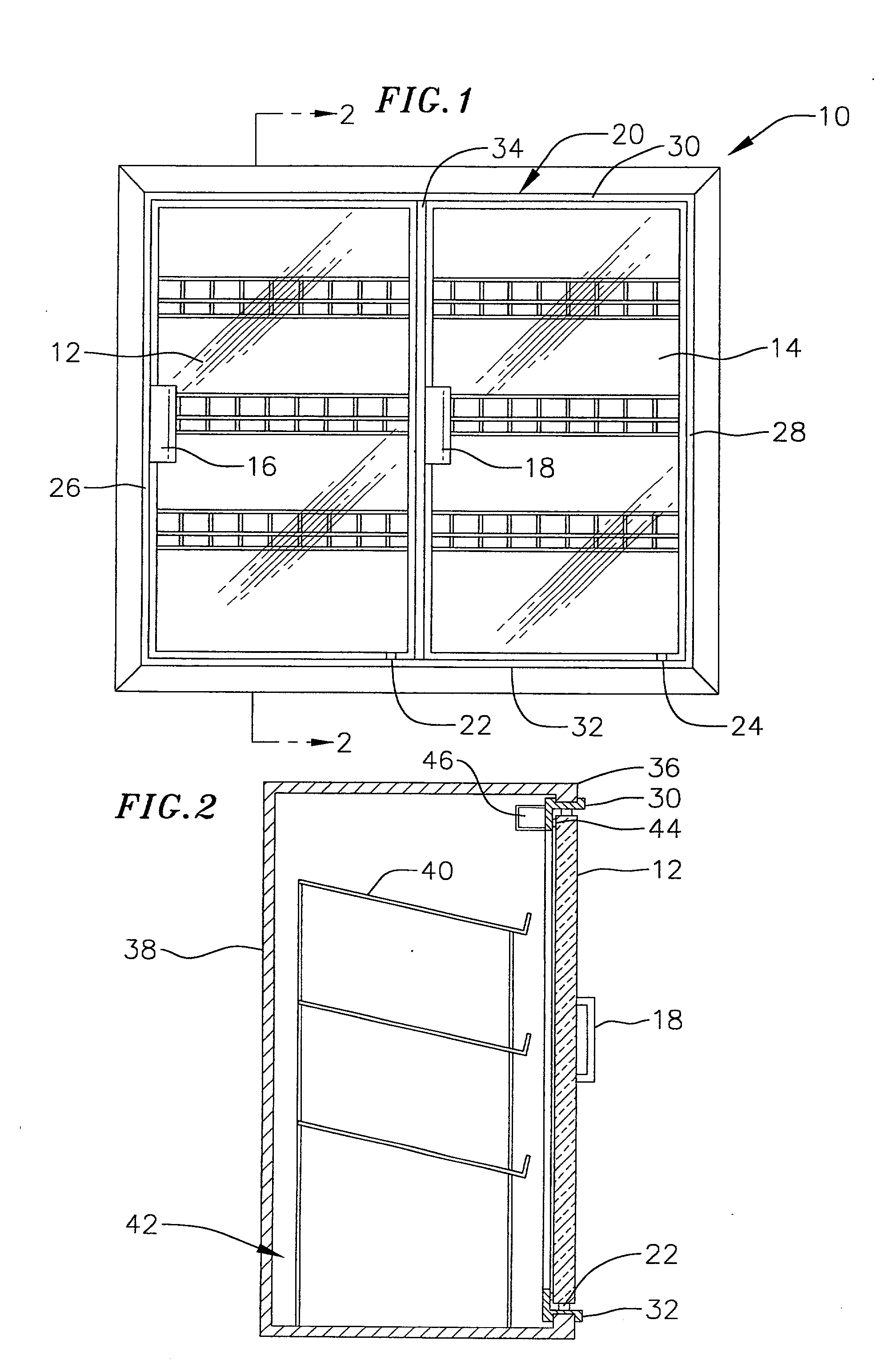
[0022] FIG. 1 illustrates one example of a refrigeration unit 10 which may be used in conjunction with, or from an element of, the present inventions. The refrigeration unit may be either a stand alone unit or a "built-in" unit. The refrigeration unit includes a pair of doors 12 and 14 which include handles 16 and 18, respectively. The doors 12 and 14 are pivotally mounted on a frame 20 by hinges 22 and 24. Frame 20 is secured to an opening in the refrigeration unit and consists ...
PUM
 Abstract
Description
Claims
Application Information