Railway car coupler knuckle having improved bearing surface

a technology for railway freight cars and couplers, which is applied in the direction of railway couplings, railway components, railway coupling accessories, etc., can solve the problems of increasing the cost of producing a satisfactory coupler, affecting the quality of the coupler, so as to achieve the effect of improving the bearing surfa

Inactive Publication Date: 2003-07-10
MCCONWAY & TORLEY LLC
View PDF15 Cites 25 Cited by
  • Summary
  • Abstract
  • Description
  • Claims
  • Application Information

AI Technical Summary

Benefits of technology

0011] It is, therefore, one of the primary objects of present invention to provide a knuckle for a railway freight car coupler having an improved bearing surface which does not require any significant grinding and / or machining of the bearing surface when compared to prior art type coupler knuckles.

Problems solved by technology

Over the years it has been discovered, in the railroad industry, that relatively small point to point contact surfaces of the engaged portions of these knuckles can cause premature failure due to stress points being established within the knuckle.
As would generally be expected by persons skilled in the art, such grinding and / or machining of such surface can add substantially to the cost of producing a satisfactory coupler.
Furthermore, it has been found that grinding the bearing surface can also establish point to point contact in a number of places and as discussed above this will add stress to the coupler knuckle.
In any case, however, prior to the conception and development of the present invention it has generally been quite difficult to provide a substantially flat surface area on these coupler knuckles.

Method used


Image

  • Railway car coupler knuckle having improved bearing surface
  • Railway car coupler knuckle having improved bearing surface
  • Railway car coupler knuckle having improved bearing surface

Examples


Embodiment Construction

, particularly, when such detailed description is taken in conjunction with the attached drawing figures and with the appended claims.

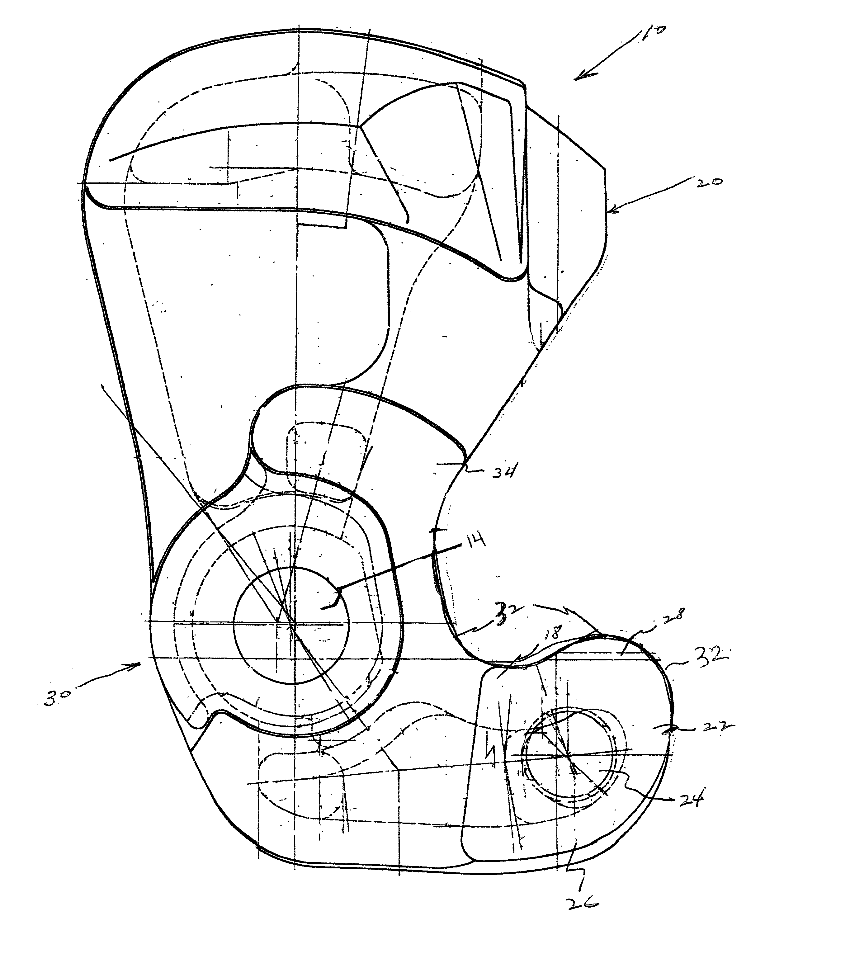
[0019] FIG. 1 is a top elevation view of a railway car coupler knuckle which has been modified in accordance with present invention; and

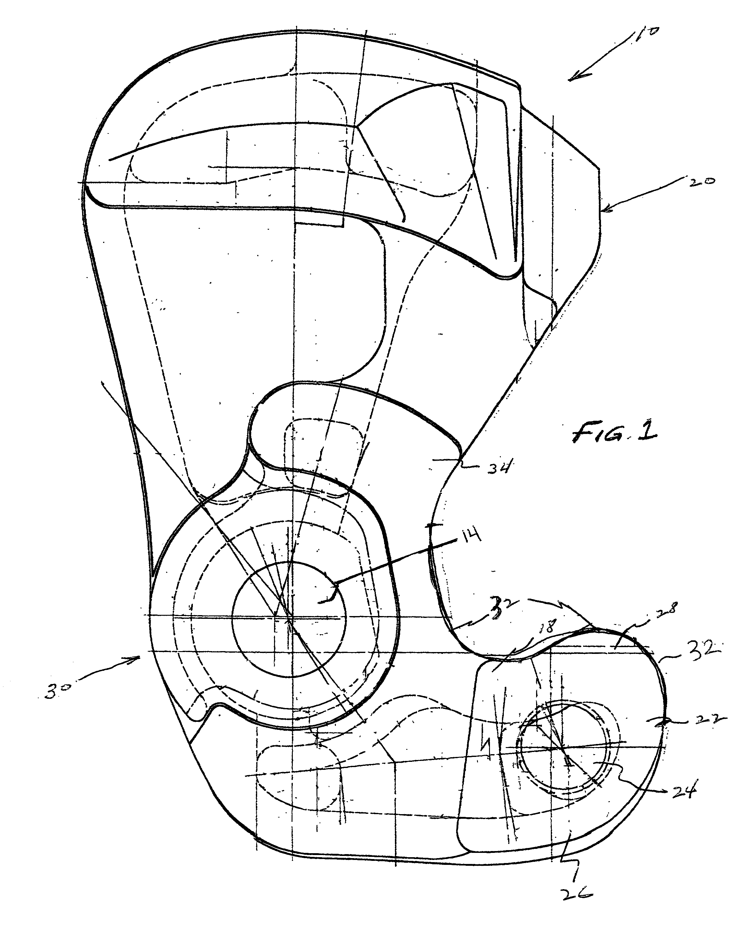
[0020] FIG. 2 is a side view of the railway car coupler knuckle illustrated in FIG. 1.

BRIEF DESCRIPTION OF A PRESENTLY PREFERRED AND VARIOUS ALTERNATIVE EMBODIMENTS OF THE INVENTION

[0021] Prior to proceeding to the much more detailed description of the present invention is should be noted that identical elements, having identical functions, have been identified with identical reference numerals throughout the several views which have been illustrated in the drawing figures for the sake of clarity and understanding of the invention.

[0022] Now reference is made, more particularly, to FIGS. 1 and 2 of the drawings. Illustrated therein and is a presently preferred embodiment of a railway freight car (not shown) coupler kn...


PUM


Abstract

A coupler knuckle casting having an enhanced bearing surface area and which is utilized in a railway freight car coupler. The coupler knuckle casting includes a tail section, and a hub section. The hub section has a pivot pinhole formed therein. Such pivot pinhole has generally straight cylindrical sidewalls. A front face section is connected to the hub section. Such front face section includes a nose section and a pulling face portion formed inwardly from such nose section. At such least a portion of such front face portion and such nose section includes an enhanced bearing surface area which includes a substantially flat portion disposed substantially in a vertical direction and which is substantially arcuate in a horizontal direction. The substantially flat portion extends for a predetermined distance in the vertical direction and for a predetermined length along the horizontal direction. There is the a transition section joining the tail section to the hub section. Such transition section includes a top metal section and a bottom metal section extending toward each other.

Description

[0001] The present invention relates, in general, to railway freight car couplers which are disposed on each end of a railway freight car and, more particularly, this invention relates to a railway freight car coupler knuckle having an improved bearing surface area for mating engagement with an adjacently disposed coupler knuckle disposed at one end of an adjacent railway freight car. Additionally, the present invention relates to a railway freight car coupler knuckle having an improved bearing surface area which can be retrofitted onto an existing railway freight car coupler.[0002] As is generally well known in the railway art, a coupler is disposed at each end of a railway car to enable joining one end of such railway car to an adjacently disposed end of another railway car. The engageable portions of these couplers is known in the railway art as a knuckle. For example, railway freight car coupler knuckles are taught in the following U.S. Pat. Nos. 4,024,958; 4,206,849; 4,605,133;...

Claims


Application Information

Patent Timeline
Patent Type & Authority Applications(United States)
IPC IPC(8): B61G3/06
CPCB61G3/06
Inventor MAUTINO, PETER S.GAGLIARDINO, JOSEPH L.
Owner MCCONWAY & TORLEY LLC
Why Eureka
Try Eureka