
Fuel injection valve

Inactive Publication Date: 2003-07-24
ROBERT BOSCH GMBH
View PDF7 Cites 5 Cited by
  • Summary
  • Abstract
  • Description
  • Claims
  • Application Information

AI Technical Summary

Benefits of technology

[0009] The fuel injector according to the present invention having the characterizing feature of the main claim has the advantage over the related art that the guidance still has a narrow tolerance. Only partial areas on the circumference of the guided component are used for flow guidance. Due to the good guidance of the valve needle, i.e., the valve closing body, wear on the fuel injector is minimized.[0010] Due to the size of the flattened areas, the axial flow component is easily adjusted. In particular, large axial flow components are feasible because this does not result in any negative effect on the guidance of the valve needle, i.e., the valve closing body.[0011] Advantageous refinements of the fuel injector according to the present invention are possible through the measures characterized in the subclaims.[0012] The simple design of variants of the fuel injector is advantageous. An individual adaptation to the specific requirements of a given internal combustion engine may be implemented while retaining most of the components.

Problems solved by technology

In the case of the fuel injector known from U.S. Pat. No. 5,108,037, the increased tolerance between the valve closing body and the guide bore is a disadvantage.
Due to the use of a spherical valve closing body and the associated linear throttling point, unavoidable fluctuations in fit are associated with a great scattering in the axial flow component.
This increases the reject rate in manufacturing the fuel injector.
Another disadvantage is the inferior guidance of the valve closing body due to the greater radial clearance between the valve closing body and the guide bore.
Flutter of the valve closing body in turn results in greater wear on the fuel injector.
In the case of the fuel injector known from German Patent Application 198 15 795 A1, however, the arrangement downstream from the sealing seat is a disadvantage.
It is therefore impossible to ensure reliable and constant processing of the fuel to be spray-discharged.
Consequently, the atomization is inferior and ultimately there is an increased pollution burden due to the inferior combustion.
This increases the manufacturing costs of the fuel injector.

Method used


Image

  • Fuel injection valve
  • Fuel injection valve
  • Fuel injection valve

Examples


Embodiment Construction

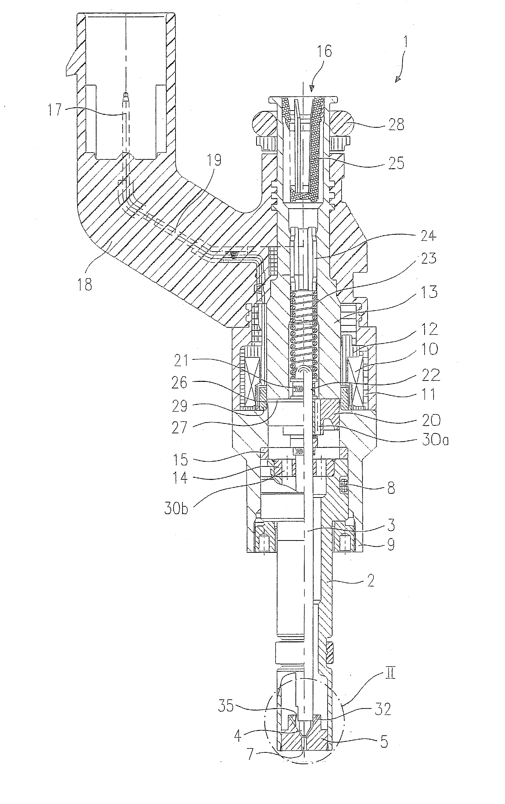
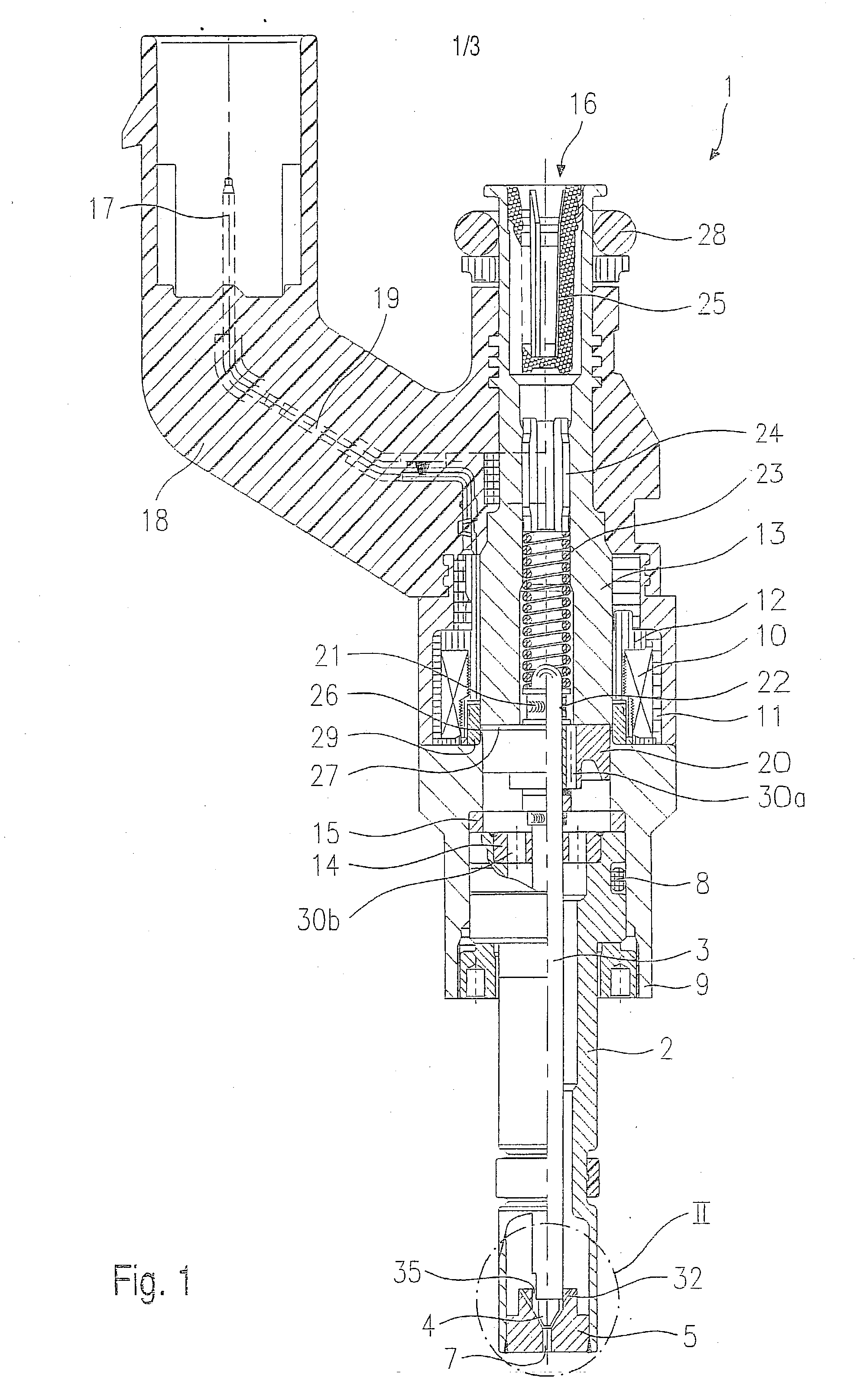
[0018] Before describing two exemplary embodiments of fuel injectors 1 according to the present invention in greater detail on the basis of FIGS. 2 through 4, fuel injector 1 according to the present invention will first be described briefly with regard to its essential components on the basis of an overall diagram in FIG. 1 to give a better understanding of the invention.

[0019] Fuel injector 1 is implemented in the form of a fuel injector 1 for fuel injection systems of internal combustion engines having compression of a gas mixture with spark ignition. Fuel injector 1 is suitable in particular for direct injection of fuel into a combustion chamber (not shown) of an internal combustion engine.

[0020] Fuel injector 1 includes a nozzle body 2 in which a valve needle 3 is arranged. Valve needle 3 is operationally linked to a valve closing body 4 which cooperates with a valve seat face 6 situated on a valve seat body 5 to form a sealing seat. In this embodiment, fuel injector 1 is an el...


PUM


Abstract

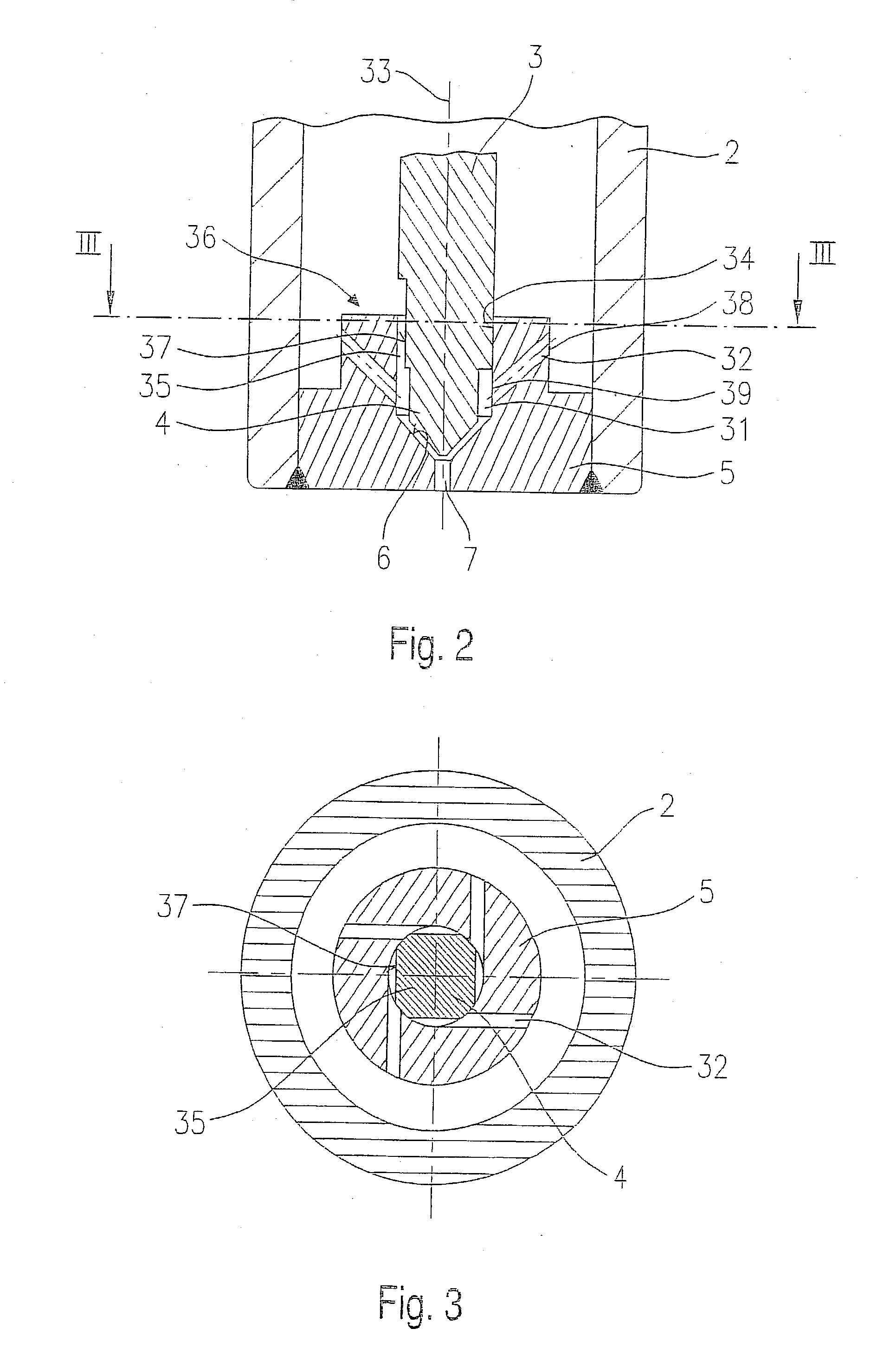
A fuel injector (1) for fuel injection systems of internal combustion engines includes a valve needle (3) and a valve closing body (4), which is operationally linked to it and cooperates with a valve seat face (6) situated in a valve seat body (5) to form a sealing seat. Upstream from the sealing seat there is at least one swirl channel (32), which has a tangential component relative to the longitudinal axis (33) of the fuel injector (1). An axial channel (35), which is formed between the valve closing body (4) and the guide recess (34) of the valve seat body (5), has an axial component relative to the longitudinal axis (33) of the fuel injector (1), the axial channel (35) being formed between the guide recess (34) and at least one flattened area (37) on the valve needle (3).

Description

BACKGROUND INFORMATION[0001] The present invention relates to a fuel injector according to the preamble of the main claim.[0002] U.S. Pat. No. 5,108,037 describes swirl-producing fuel injectors in which two flow paths are formed for the fuel. The fuel flow is split into two components in the area of the valve closing body. One component of the fuel flows through swirl channels arranged in a swirl disk. The fuel flow is imparted at a circumferential velocity which results in fuel being spray-discharged onto a conical envelope. The swirl disk has a central bore which is used to guide the valve closing body. The gap formed between the guide bore and the valve closing body is utilized in a targeted manner to permit a fuel leakage flow which flows without swirl in the axial direction through the guide bore. Upstream from the sealing seat, the axial fuel flow encounters the fuel flow in which a swirl has been induced. The fuel flows combine and are spray-discharged jointly. Therefore, fue...

Claims


Application Information

Patent Timeline
IPC IPC(8): F02B75/12F02M51/06F02M51/08F02M61/12F02M61/16F02M61/18
CPCF02B2075/125F02M51/0671F02M61/12Y02T10/123F02M61/168F02M61/18F02M61/162Y02T10/12
Inventor DANTES, GUENTERNOWAK, DETLEFHEYSE, JOERG
Owner ROBERT BOSCH GMBH
Learn More