Electrochromic layer

a technology of electrochromic devices and layers, applied in the field of electrochromic devices, can solve the problems of patents not providing electrochromic devices suitable for large-scale in wide variety of uses and applications, and the most sensitive to ultraviolet light and weathering degradation

Inactive Publication Date: 2003-07-24
ECLIPSE ENERGY SYST
View PDF53 Cites 40 Cited by
  • Summary
  • Abstract
  • Description
  • Claims
  • Application Information

AI Technical Summary

Problems solved by technology

Unfortunately, organic emulsions are the most sensitive to ultraviolet light and weathering degradation.
Although the aforementioned patents have made advancement

Method used


Image

  • Electrochromic layer
  • Electrochromic layer
  • Electrochromic layer

Examples


Embodiment Construction

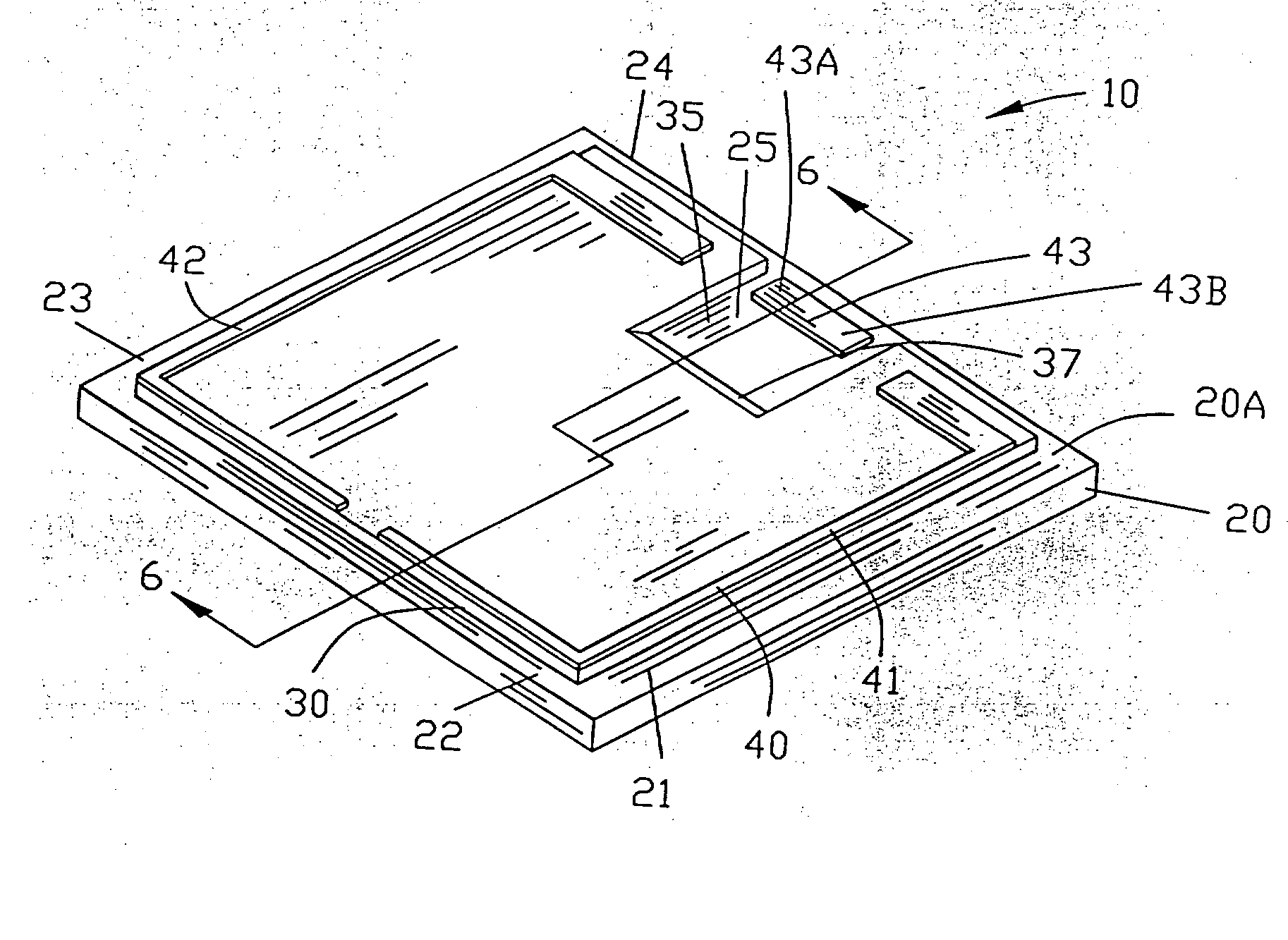
[0062] FIGS. 1-16 are various views illustrating the method of forming an electrochromic device 10 of the present invention. The method of forming the improved electrochromic device 10 includes at least one of the layers being deposited by vacuum deposition or by plasma enhanced chemical vapor deposition (PECVD).

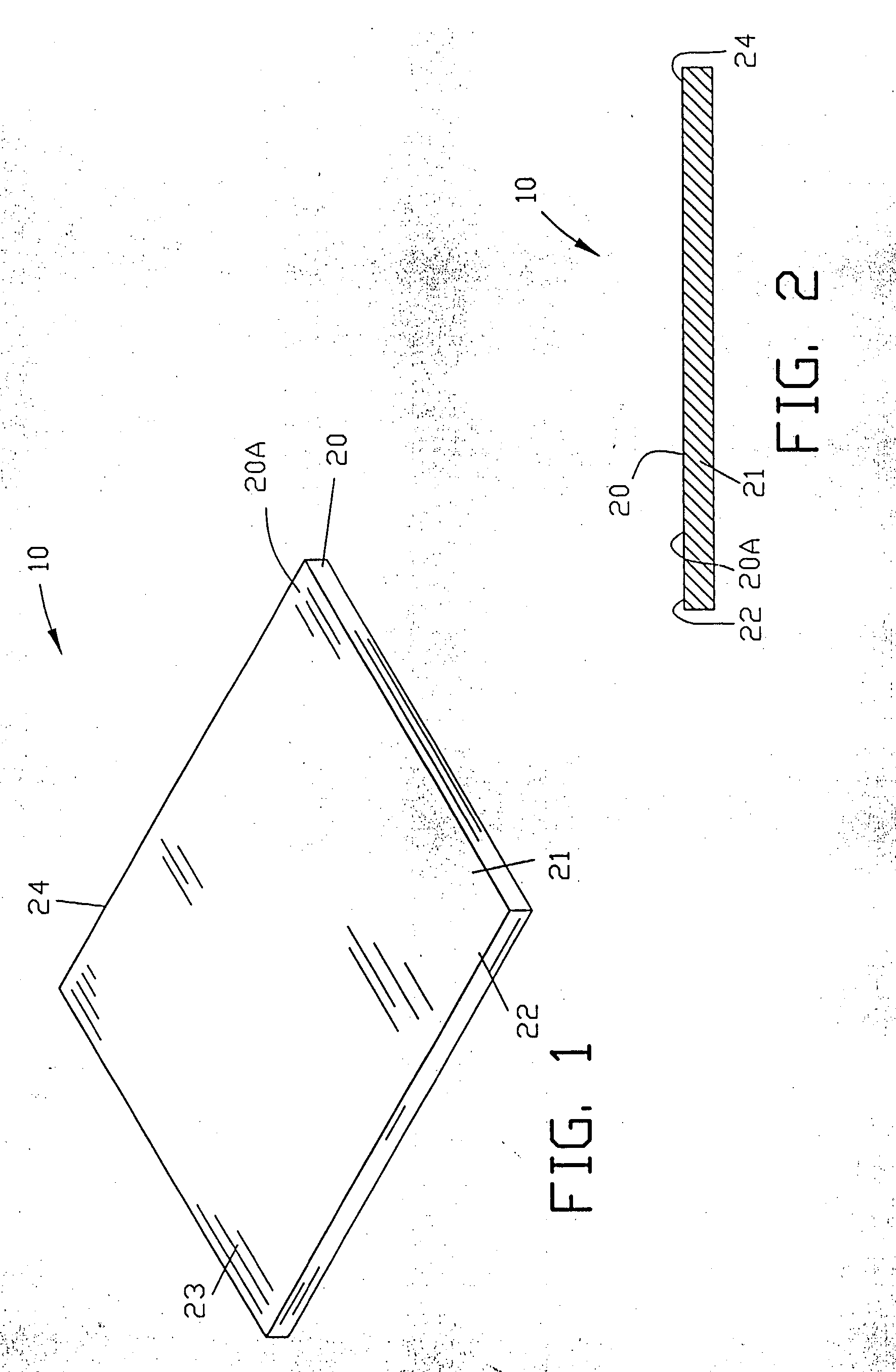
[0063] FIGS. 1 and 2 illustrate a substrate 20 of the electrochromic device 10. The substrate is defined by a top surface 20A and peripheral edges 21-24. Preferably, the substrate 20 is substantially transparent. In a more specific example of the invention, the substrate 20 may be a rigid material such as glass or may be a flexible material such as a polymeric material.

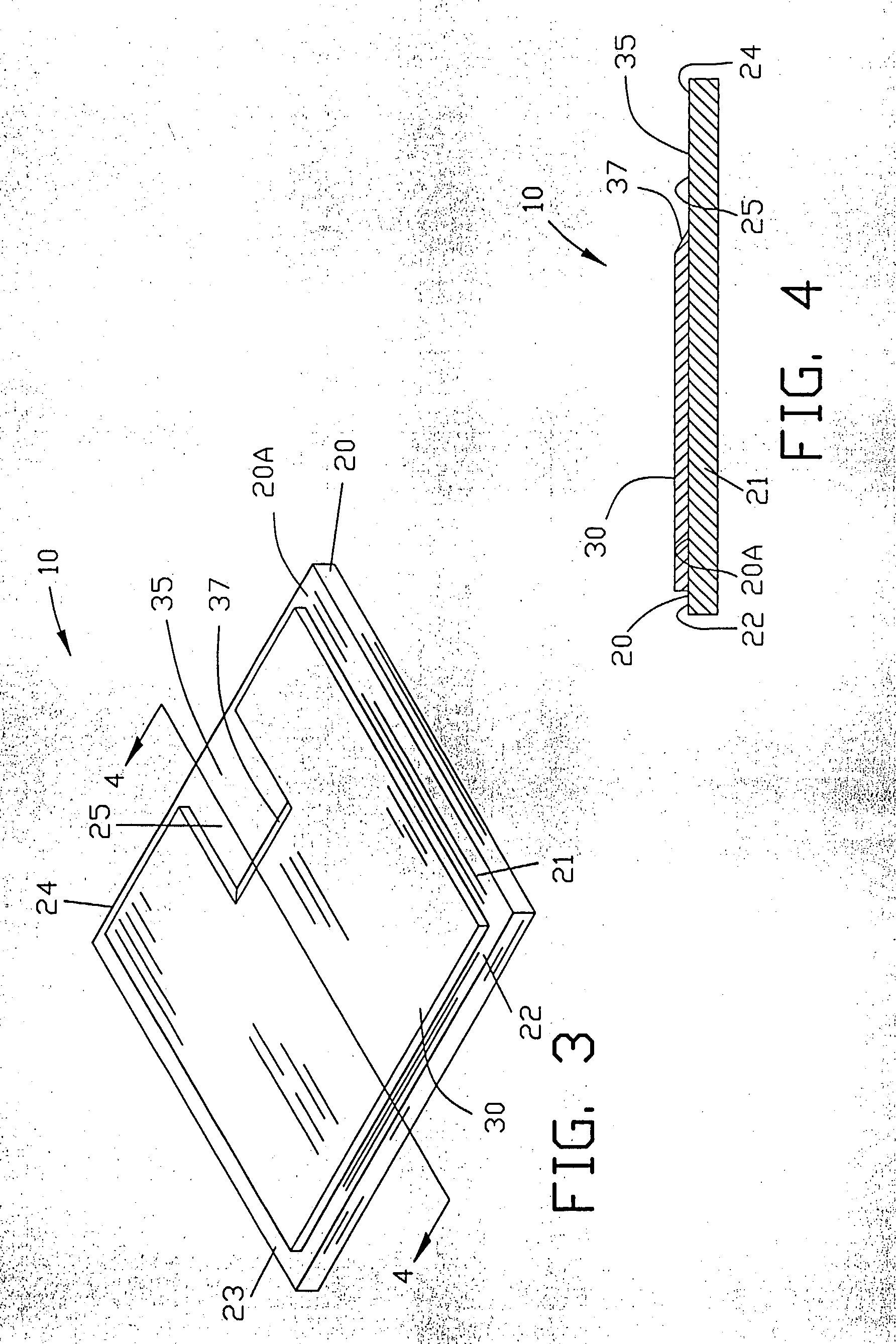
[0064] FIGS. 3 and 4 illustrate the deposition of a first conductive layer 30 located on the transparent substrate 20. The first conductive layer 30 covers the top surface 20A of the substrate 20 except for a narrow strip around the peripheral edges 21-24 of the substrate 20 and a rectangular area 25. Preferab...


PUM


Abstract

An improved electrochromic device comprising a substrate and a first conductive layer located on the transparent substrate. An ion storage layer is located on the first conductive layer. An electrolyte layer is located on the ion storage layer with an active layer being located on the electrolyte layer. A second conductive layer is located on the active layer

Description

[0001] This application claims benefit of U.S. Patent Provisional application serial No. 60 / 187,704 filed Mar. 7, 2000. All subject matter set forth in provisional application serial No. 60 / 187,704 is hereby incorporated by reference into the present application as if fully set forth herein.[0002] 1. Field of the Invention[0003] This invention relates to variable reflective and variable transmission layers and more particularly to an improved electrochromic device with superior variable reflective and variable transmission properties.[0004] 2. Background of the Related Art[0005] Electrochromic devices operate in a manner similar to the operation of a battery. In a battery, electrons or ions are stored in layers of materials commonly referred to as battery plates. The ions are available to move to perform work when connected to an external electrical circuit.[0006] An electrochromic device has an electron / ion storage layer and an electron / ion active layer. In the electrochromic devic...

Claims


Application Information

Patent Timeline
IPC IPC(8): G02F1/1524G02F1/155H01M6/18
CPCG02F1/1523H01M6/18G02F1/155G02F1/1525G02F1/1524
Inventor WESTFALL, RAYMOND T.KISLOV, NIKOLAI
Owner ECLIPSE ENERGY SYST
Why Eureka
Try Eureka