Recording plate or film loading device

Inactive Publication Date: 2003-07-31
FUJIFILM ELECTRONICS IMAGING
View PDF5 Cites 2 Cited by
  • Summary
  • Abstract
  • Description
  • Claims
  • Application Information

AI Technical Summary

Problems solved by technology

However, these cassettes are expensive and in many cases users prefer manually to load plates or films.
A drawbac

Method used


Image

  • Recording plate or film loading device
  • Recording plate or film loading device
  • Recording plate or film loading device

Examples


Example

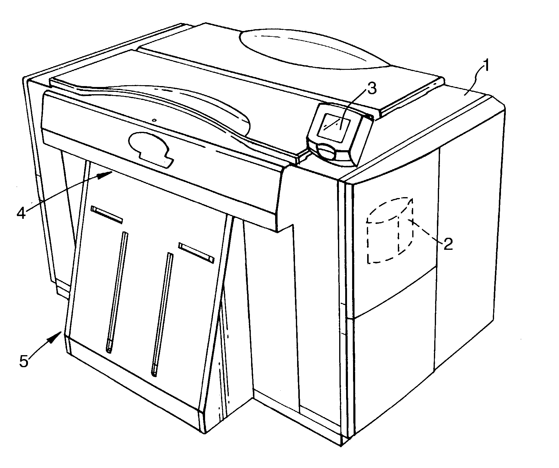
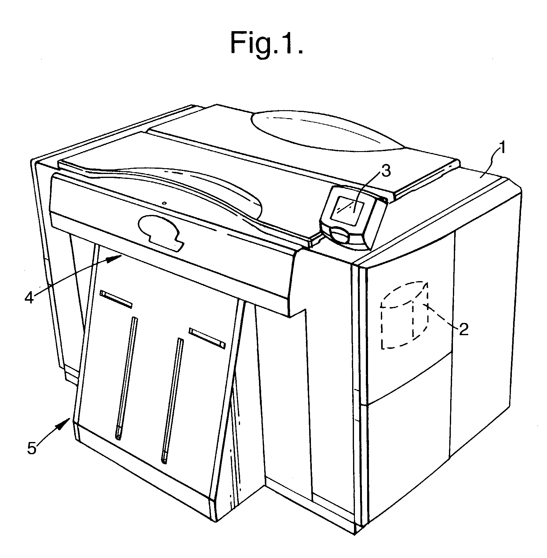
[0019] The apparatus shown in FIG. 1 comprises an internal drum image scanner 1 of conventional construction (for example as shown in WO-A-99 / 17535) having a control computer 2 mounted internally for controlling operation of the scanner. The control computer 2 is also connected to an illuminated control panel 3 mounted at the top of the scanner 1 for receiving inputs via a touch screen and displaying information. The scanner 1 has an input slot 4 for receiving individual plates or film sheets to be exposed.

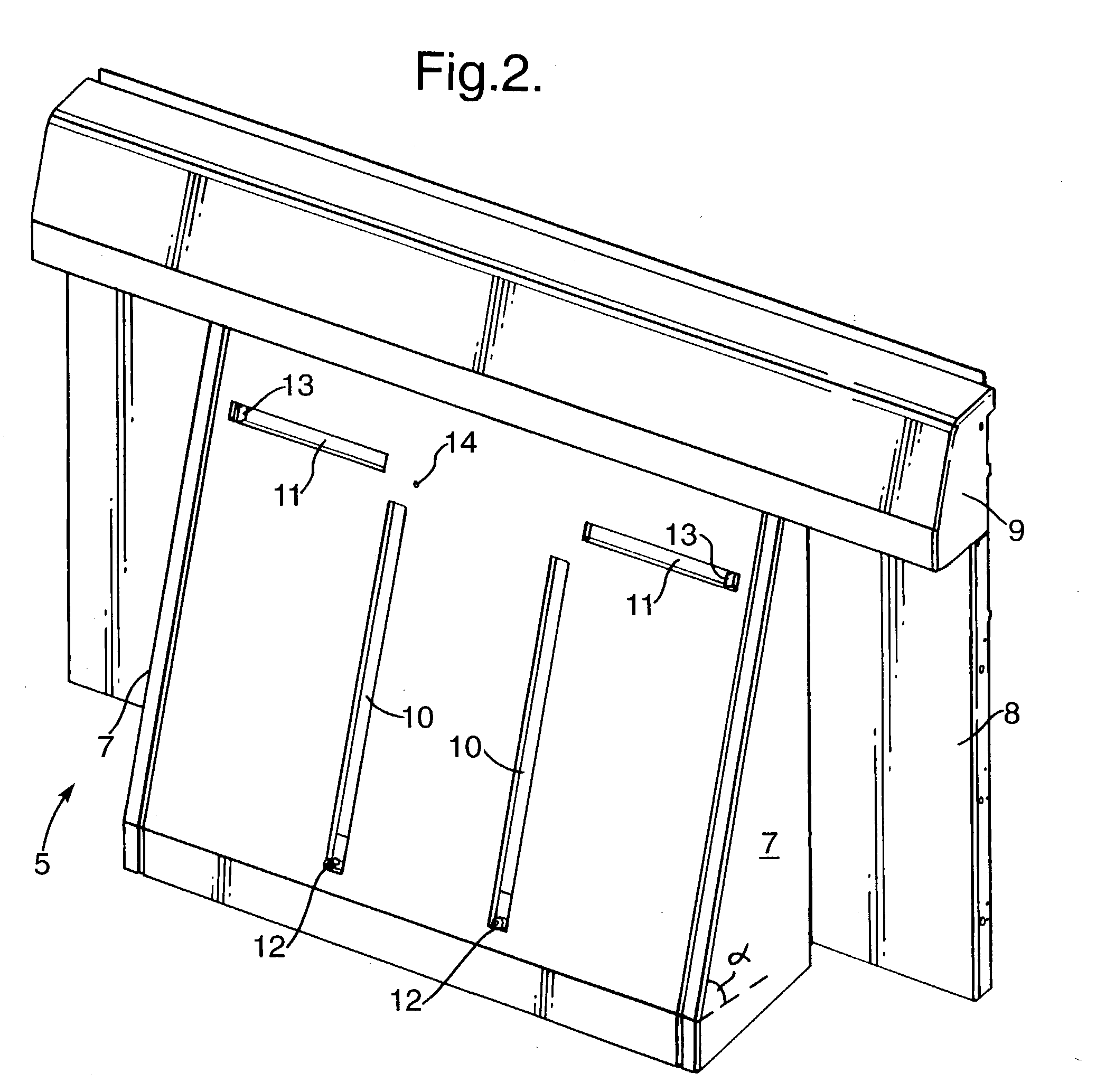
[0020] A recording plate or film loading device 5 is mounted to the front of the scanner 1 and this is shown in more detail in FIG. 2. The device 5 comprises a platen 6 mounted at an angle .alpha. to the horizontal of 71.degree.. The platen is mounted by means of side plates 7 to a back plate 8 and extends beneath an air curtain 9. A plate or film sheet exits from behind the air curtain 9 and passes into the slot 4.

[0021] The platen 6 has a pair of laterally spaced upwardly extend...


PUM

PropertyMeasurementUnit
Angleaaaaaaaaaa
Angleaaaaaaaaaa
Angleaaaaaaaaaa

Abstract

A recording plate or film loading device for use with an image recording scanner. The device comprises a platen (6) arranged at an angle to the horizontal and onto which a plate or film is manually placed. A loading mechanism includes one or more first pusher members (12) cooperating with the platen to push a plate or film to an output position. A centering mechanism includes a pair of second pusher members (13) movable laterally with respect to the platen (6) to centre a plate or film on the platen.

Description

[0001] The invention relates to a recording plate or film loading device for use with an image recording scanner.DESCRIPTION OF THE PRIOR ART[0002] Modern image recording scanners have been developed which can record images onto a plate or film having dimensions up to 1200.times.1000 mm. By a recording plate or film we include any conventional imaging media such as photographic film, polyester plate, paper, aluminium plate etc. In some cases, a stack of unexposed plates or film sheets is provided in a cassette from which they are automatically loaded into the image recording scanner such as an internal drum imaging scanner (see for example EP-A-0822454). However, these cassettes are expensive and in many cases users prefer manually to load plates or films. This also has the advantage that successive images can be recorded on different size plates. In typical manual devices, a large, horizontal table is positioned adjacent the image recording scanner. The user places the unexposed fi...

Claims


Application Information

Patent Timeline
IPC IPC(8): B41C1/00B65H5/16B65H9/10B65H11/00G03F7/24G03F9/00H04N1/00
CPCB65H5/16B65H9/101B65H11/00B65H2701/1928B65H2301/36112B65H2301/36212B65H2301/324
Inventor PANKHANIA, JAG
Owner FUJIFILM ELECTRONICS IMAGING
Why Eureka
Try Eureka