Check bit free error correction for sleep mode data retention

a technology of sleep mode and error correction, applied in the field of dynamic random access memories of semiconductors, can solve the problems of data loss, large power consumption of display screens and mechanical disk drive systems, and relatively inexpensive srams to fabrica

a technology of sleep mode and error correction, applied in the field of dynamic random access memories of semiconductors, can solve the problems of data loss, large power consumption of display screens and mechanical disk drive systems, and relatively inexpensive srams to fabrica

US20030149929A1Active Publication Date: 2003-08-07IBM CORP

Image

  • Check bit free error correction for sleep mode data retention
  • Check bit free error correction for sleep mode data retention
  • Check bit free error correction for sleep mode data retention

Examples


Embodiment Construction

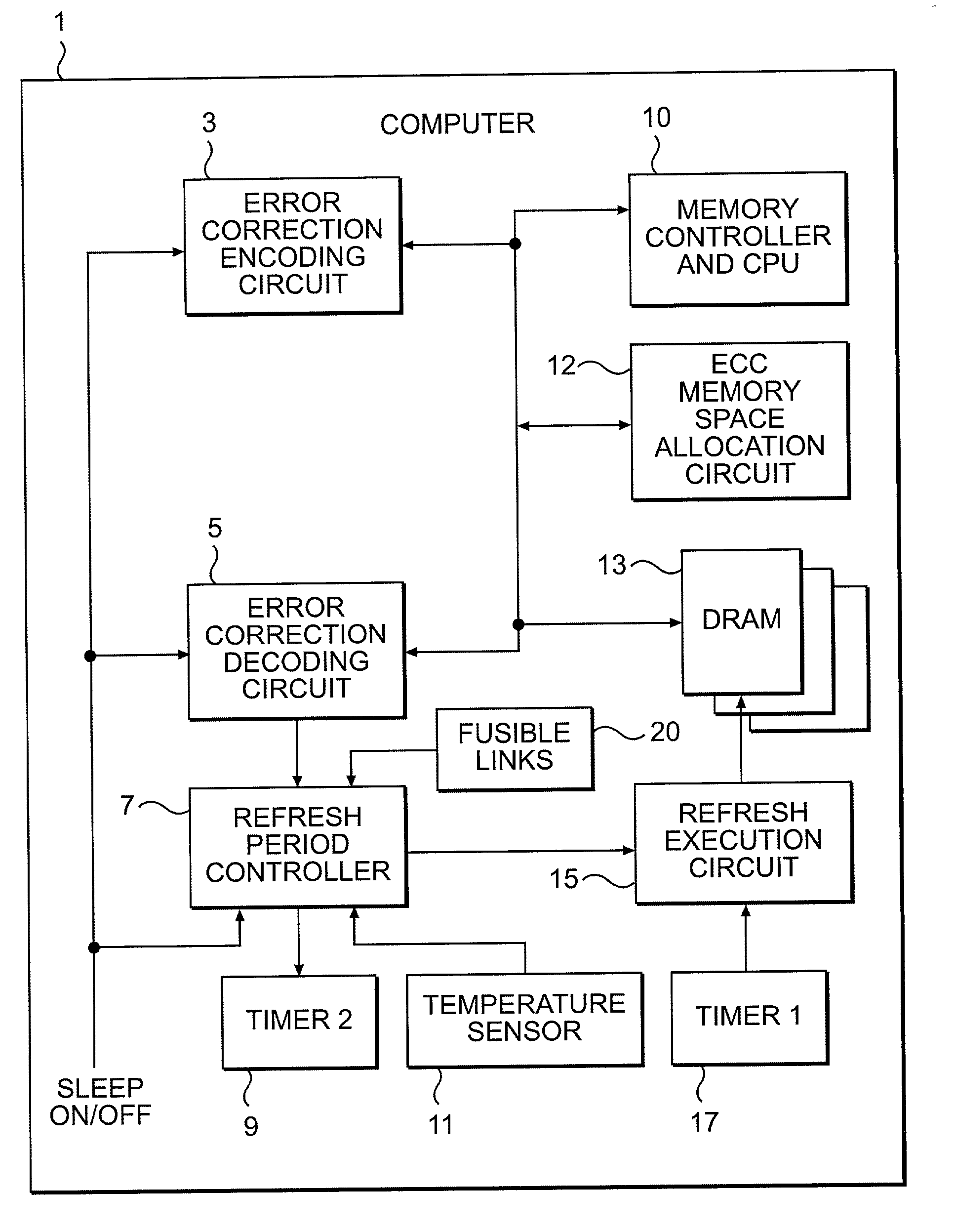
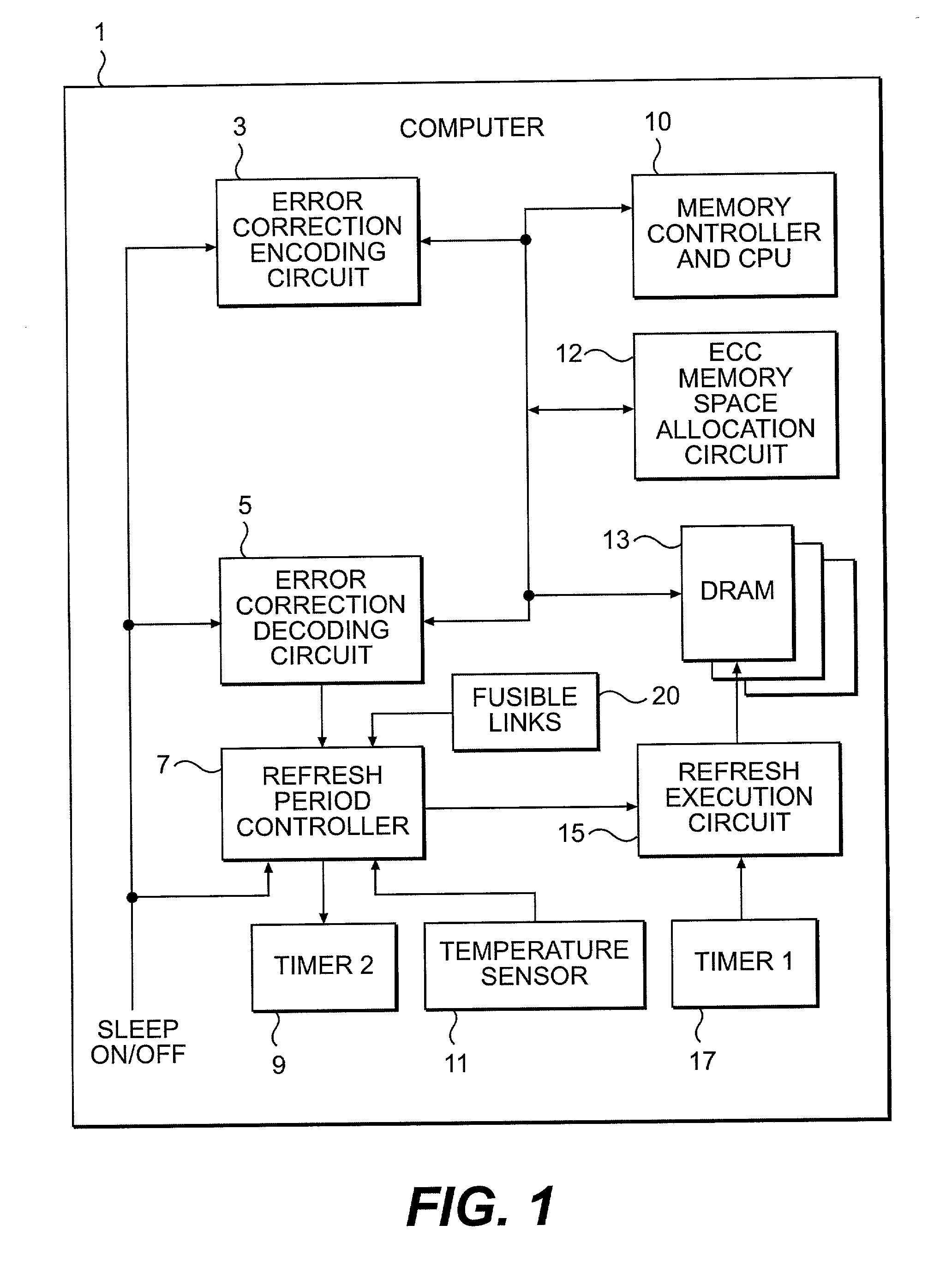
[0018] Referring now to the drawings, and more particularly to FIG. 1, there is shown a block diagram illustrating a computer 1 including a memory system according to the present invention. A plurality of DRAMs 13 are connected to a memory controller and a CPU 10, an error correction encoding circuit 3, an error correction decoding circuit 5, and a refresh execution circuit 15. The error correction encoding circuit 3 and the error correction decoding circuit 5 receive sleep ON and OFF signals. The refresh period controller 7 is connected to the error correction decoding circuit 5, a timer 2 (9), and a temperature sensor 11. The refresh period controller 7 also receives sleep ON and OFF signals. The refresh execution circuit 15 is connected to the refresh period controller 7 and a first timer 17. In operation, the first timer 17 times the refresh period in active mode. When in a sleep mode, the second timer 9 is used to time the reduced refresh rate. If the temperature sensor 11 is e...


PUM


Abstract

A DRAM memory has a reduced refresh rate in a sleep mode to conserve power. Error Correction Codes (ECC) are used to correct errors that may arise due to the reduced refresh rate. ECC encoding occurs at the time of entering the sleep mode and ECC decoding for error detection and correction need only take place upon wake up when resuming active mode. In addition, the memory system reassigns a portion of the memory for storing the additional parity bits required for the error correcting code (ECC).

Description

[0001] 1. Field of the Invention[0002] The present invention generally relates to semiconductor dynamic random access memories (DRAMs) and, more particularly, to correcting bit errors arising during sleep mode due to a reduced DRAM refresh rate.[0003] 2. Description of the Related Art[0004] There are two common families of RAM memory devices used as primary storage directly accessible by the microprocessor. The first, static random access memory devices (SRAMs) are based on flip-flop circuits and retain data as long as power is supplied. The second, dynamic random access memory devices (DRAMs), store data as a function of a charge on a capacitor. The capacitors must constantly be refreshed since the charge dissipates. Both have advantages and disadvantages. DRAMs are relatively inexpensive to fabricate but are slow as compared to SRAMs. SRAMs are therefore typically reserved for use as caches. DRAMs, on the other hand, are relatively inexpensive providing a lower cost per bit and ar...

Claims


Application Information

Patent Timeline
07 Aug 2003
Publication
US20030149929A1
IPC
G06F11/10; G11C11/406
CPC
G06F11/106; G11C2207/2227; G11C11/406
Inventors
WHITE, KRAIG R.