Radar device and method for coding a radar device

Inactive Publication Date: 2003-08-14
ROBERT BOSCH GMBH
View PDF0 Cites 77 Cited by
  • Summary
  • Abstract
  • Description
  • Claims
  • Application Information

AI Technical Summary

Problems solved by technology

Since the transition of the phase relation in the actual setup does not occur instantaneously, errors occur after the integration of the signal.
Since the transition of the phase relation in the actual setup does not occur instantaneously, errors occur after the integration of the signal

Method used


Image

  • Radar device and method for coding a radar device
  • Radar device and method for coding a radar device
  • Radar device and method for coding a radar device

Examples


Embodiment Construction

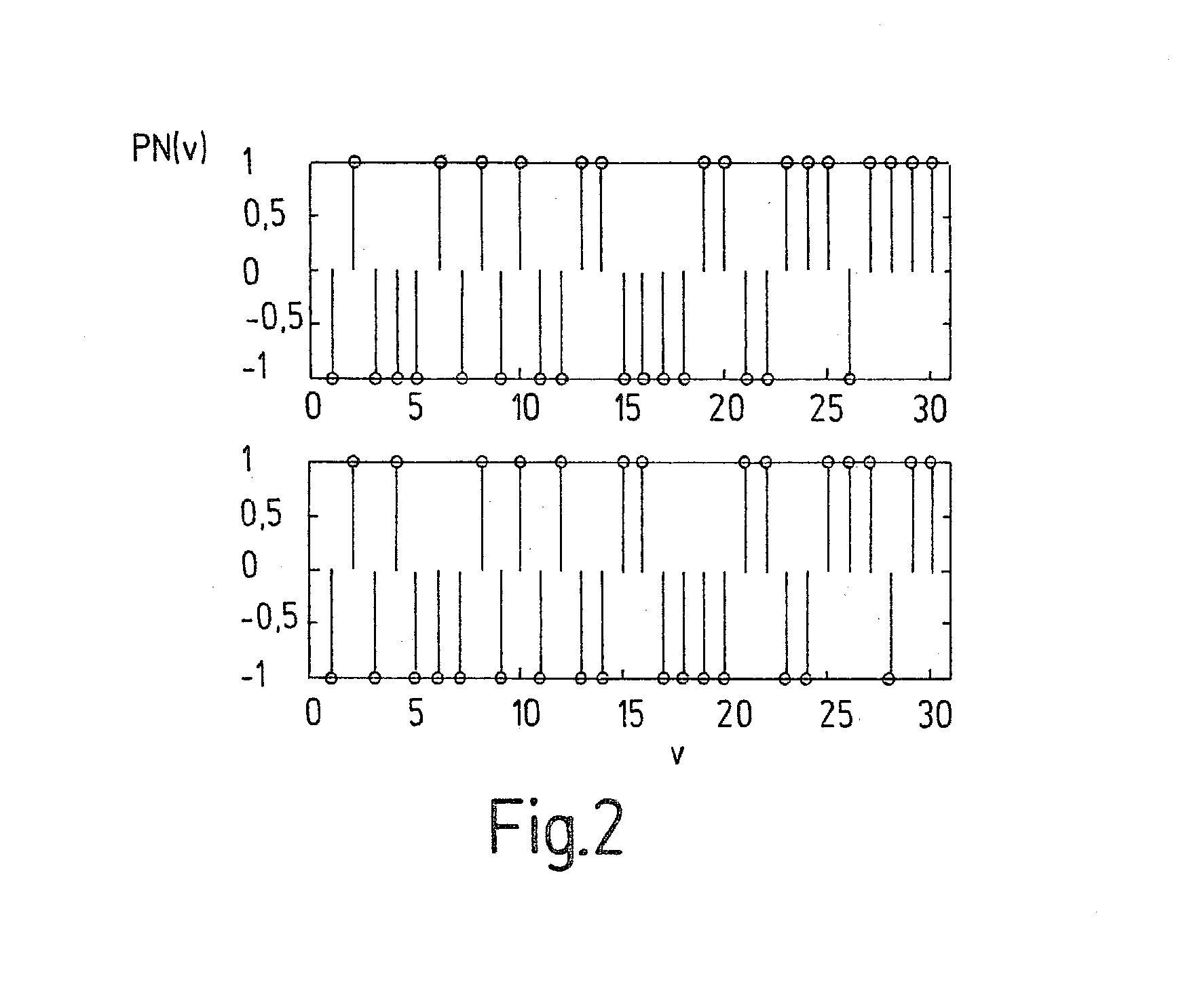
[0068] FIG. 2 shows segments of PN codes. In the upper part of FIG. 2, a PN code is shown as a function of parameter v. The lower part of FIG. 2 shows the same PN code with a shifting by v=2. Such PN codes and their shifting are used, within the framework of the present invention, for improving the S / N ratio and the ratio of useful signal to Doppler leakage signal. Basically, such an improvement is achieved by increasing the pulse repetition rate f.sub.PW. However, the maximum pulse repetition rate is limited by the range of the radar: 1 f PW , max = c 2 R max with f PW , max being the maximum pulse repetition rate , c being the speed of light , R max being the range of the radar .

[0069] Targets at distances beyond R.sub.max are not detected. If the pulse repetition rate is increased, the measurement for target distances between C / (2f.sub.PW) and R.sub.max is no longer definite. Within the framework of the present invention, however, one successfully achieves the S / N ratio by increa...


PUM


Abstract

The present invention relates to a radar system having means (12) for producing a code, means (18) for modulating a transmission signal in a transmit branch, using the code, means (32) for delaying the code, means (20) for modulating a signal in a receive branch, using the delayed code, and means (26) for mixing a reference signal with a receiving signal, the modulation of one of the signals being performed by an amplitude modulation (ASK; "amplitude shift keying") and the modulation of the other signal by a phase modulation (PSK; "phase shift keying"). Furthermore, a radar system is proposed in which blanking of phase transitions is provided. The present invention also relates to methods which may advantageously be carried out, using the radar systems according to the present invention.

Description

[0001] The present invention relates to a radar system having means for producing a code, means for modulating a transmission signal in a transmit branch using the code, means for delaying the code, means for modulating a signal in a receive branch using the delayed code, and means for mixing a reference signal with a receiving signal. The present invention also relates to a method for coding a radar system having the steps: generating a code, modulating a transmission signal in a transmit branch using the code, delaying the code, modulating a signal in a receive branch using the delayed code, and mixing a reference signal with a receiving signal.BACKGROUND INFORMATION[0002] There are numerous applications for radar systems in the most varied fields of technology. For instance, it is possible to install radar sensors in motor vehicles for very short range sensor systems.[0003] In radar systems, in principle, electromagnetic waves are radiated by a transmission antenna. If these elec...

Claims


Application Information

Patent Timeline
IPC IPC(8): G01S13/02G01S13/22G01S13/28
CPCG01S7/023G01S13/288G01S13/222G01S7/0234G01S7/0235
Inventor STEINLECHNER, SIEGBERTBROSCHE, THOMAS
Owner ROBERT BOSCH GMBH
Why Eureka
Try Eureka