Sensor arrangement

a technology of sensors and arranged parts, applied in the direction of electric devices, apparatus for force/torque/work measurement, vehicular safety arrangements, etc., can solve the problems of preventing rapid detection, preventing recognition of fixed-pole crash into the door of the vehicle too late, and preventing separation

Inactive Publication Date: 2003-08-21
ROBERT BOSCH GMBH
View PDF3 Cites 11 Cited by
  • Summary
  • Abstract
  • Description
  • Claims
  • Application Information

AI Technical Summary

Problems solved by technology

Particularly in the case of lateral collisions, the known acceleration sensors have the disadvantage that they permit rapid detection of a crash only if the sensor is directly struck.
Thus, for example, when installed on the B-pillar, a fixed-pole crash into the door of the vehicle is recognized too late.
Pressure sensors, known by themselves, also cause problems with respect to a separation of the triggering and non-triggering conditions when installed at these locations, since they should not respond, for instance, to heavy door slamming.
Furthermore, in the case of a collision, the velocity of the intrusion by the obstacle is also a decisive factor which determines the severity of the accident and the danger of injury for the occupants.

Method used


Image

  • Sensor arrangement
  • Sensor arrangement
  • Sensor arrangement

Examples


Embodiment Construction

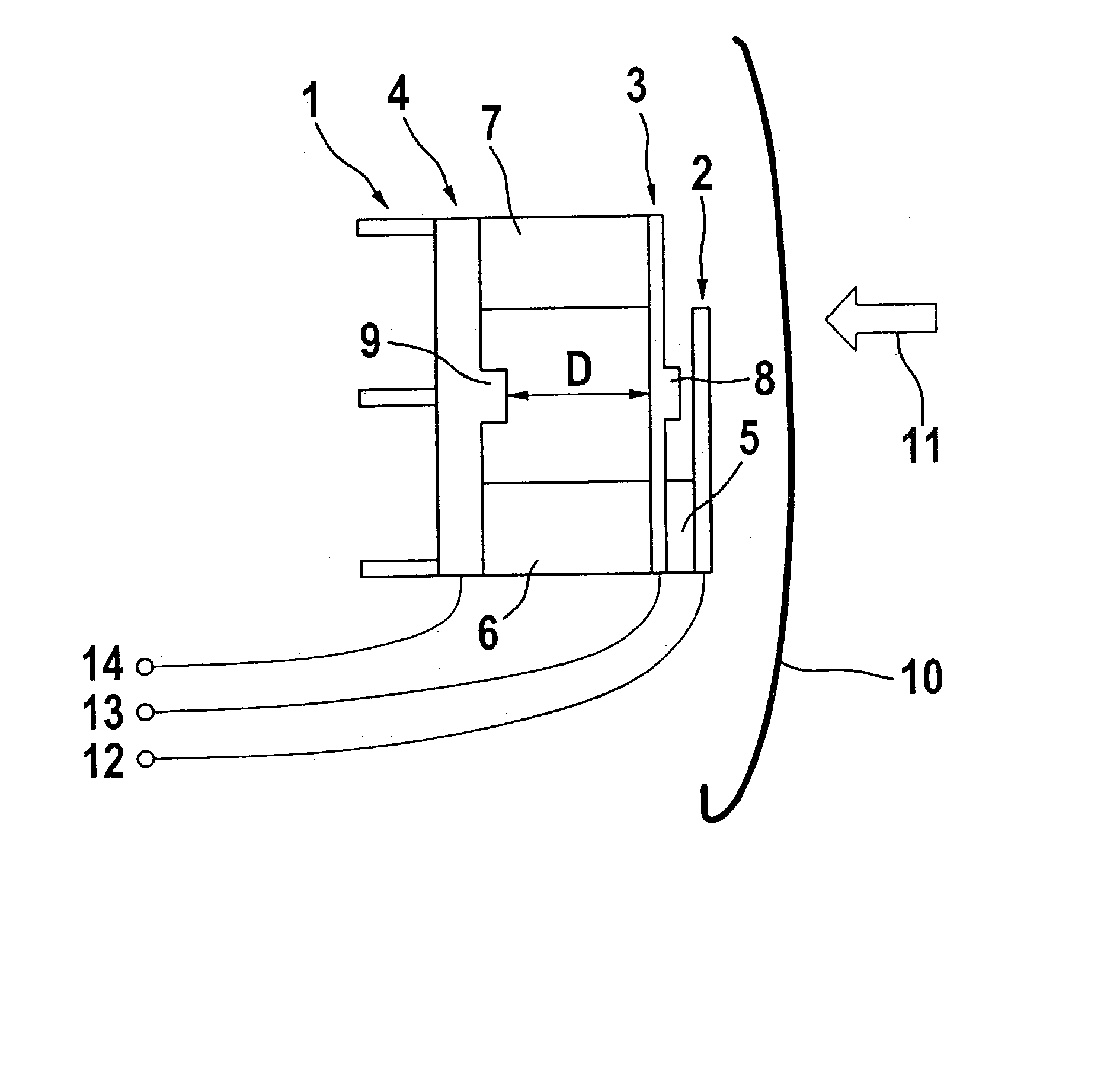
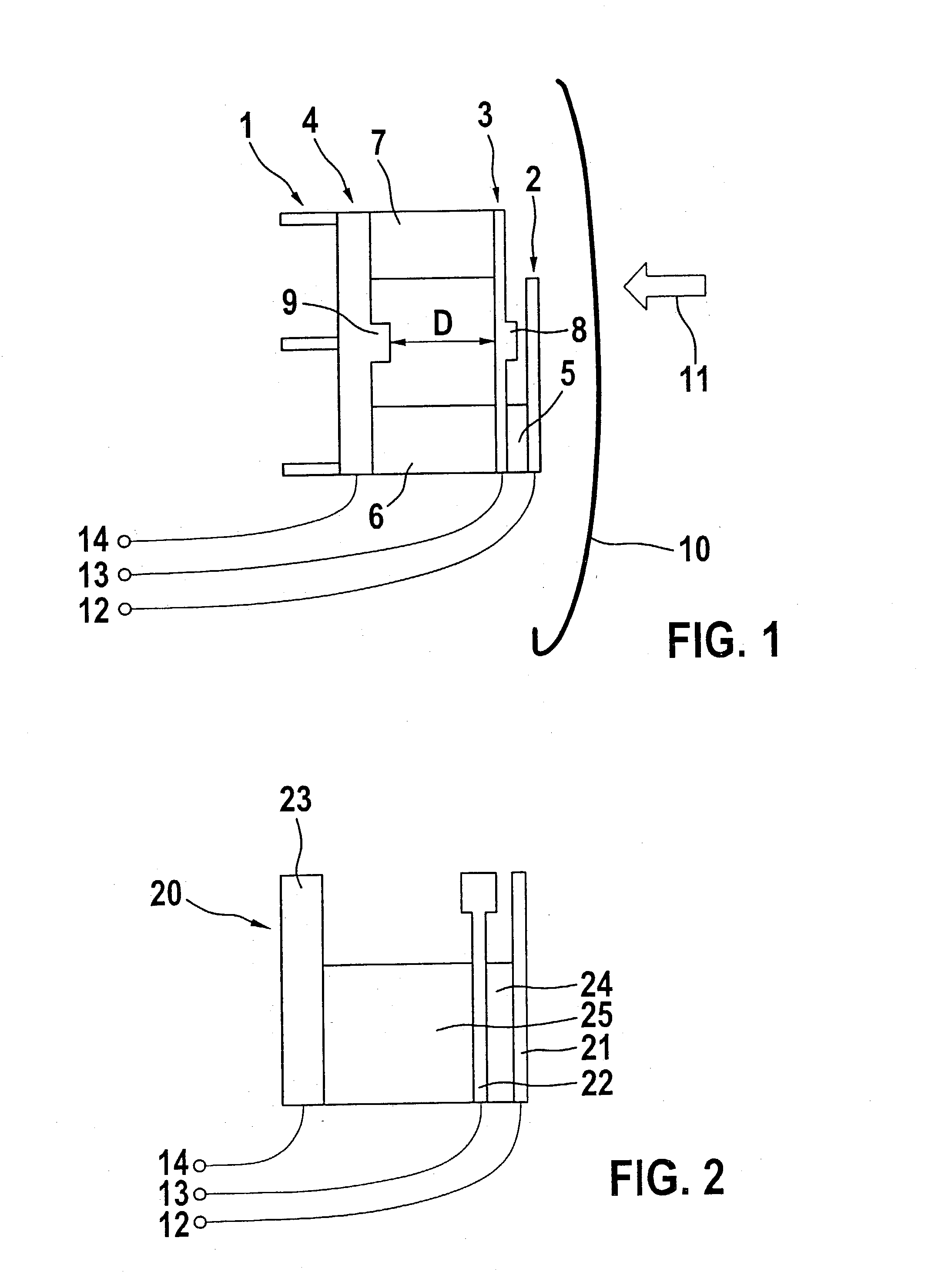
[0037] An exemplary embodiment of a sensor system 1 according to FIG. 1 shows an upper electroconductive contact element 2, a middle electroconductive contact element 3 and a third electroconductive contact element 4 as base element. Situated between contact elements 2, 3 and 4 are compressible insulation layers 5, 6 and 7 made, for example, of foamed plastic, which spatially separate contact elements 2, 3 and 4 at a predefined distance, distance D between middle contact element 3 and base element 4 in particular being significant here for the evaluation of the sensor signals.

[0038] Sensor system 1 is installed, for example, in door trim 10 of a motor vehicle (not shown here), and is able to be deformed in a direction 11 during an accident. Contact elements 2, 3 and 4, possibly with bars 8 and 9, are provided in such a way that an electrical contact is ensured between these elements 2, 3 and 4 in response to complete compression of insulation layers 5, 6 and 7 because of a crash.

[00...


PUM

PropertyMeasurementUnit
velocityaaaaaaaaaa
compressibleaaaaaaaaaa
distancesaaaaaaaaaa

Abstract

A sensor system (1; 20; 30; 40) is proposed for detecting forces which, particularly in the case of a motor vehicle, lead to a deformation of components, e.g. body parts (10) as the result of an accident. The sensor system (1; 20; 30; 40) has a number of contact elements (2, 3, 4; 21, 22, 23; 31, 32, 33) which are arranged on the component (10) staggered one behind the other in a possible deformation direction (11), compressible insulation layers (5, 6, 7; 24, 25; 35, 36) being disposed between the contact elements (2, 3, 4; 21, 22, 23; 31, 32, 33). The contact elements (2, 3, 4; 21, 22, 23; 31, 32, 33) are electroconductively connected to an electronic evaluation circuit by which a contacting and/or de-contacting of adjacent contact elements (2, 3, 4; 21, 22, 23; 31, 32, 33), caused by a deformation, is able to be detected and converted into control and or regulating signals.

Description

BACKGROUND INFORMATION[0001] The present invention relates to a sensor system, particularly for detecting mechanical forces which, for example, during a collision of a motor vehicle with an obstacle, lead to an intrusion or deformation of components on this motor vehicle.[0002] Such sensor systems are used, for example, for so-called occupant-restraint systems in motor vehicles which, for instance, trigger airbags accidents to protect the vehicle occupants from the results of a collision. For triggering these occupant-restraint systems, for example, the acceleration in the passenger compartment or at peripheral regions of the motor vehicle is measured. In addition to the sensor or sensors in the passenger compartment, the peripheral sensors are, as a rule, preferably installed at the deformable areas of the vehicle. Thus, for example, for better and early recognition of lateral collisions, acceleration sensors are installed on the so-called B-pillar and / or C-pillar of the vehicle, o...

Claims


Application Information

Patent Timeline
Patent Type & Authority Applications(United States)
IPC IPC(8): G01L1/12B60R21/01B60R21/16G01L1/20G01L5/00G01P3/02G01P3/12G01P3/50H01H3/16H01H9/04H01H35/00H01H35/14H03M1/78
CPCB60R21/0136G01P3/02G01P3/50Y10S200/10H01H35/146H03M1/785H01H35/006
Inventor STUETZLER, FRANK-JUERGEN
Owner ROBERT BOSCH GMBH
Why Eureka
Try Eureka