Preheated fuel and oxidant combustion burner

a technology of oxidant combustion and preheated fuel, which is applied in the direction of combustion types, combustion using lumps and pulverulent fuels, lighting and heating apparatuses, etc., can solve the problems of reducing the thermal efficiency of air-fuel heat recovery systems, not using pure oxygen, and creating explosive conditions

Inactive Publication Date: 2003-08-21
LAIR LIQUIDE SA POUR LETUDE & LEXPLOITATION DES PROCEDES GEORGES CLAUDE +1
View PDF6 Cites 47 Cited by
  • Summary
  • Abstract
  • Description
  • Claims
  • Application Information

AI Technical Summary

Benefits of technology

[0031] e) with the provision that the conduit adapted to convey preheated fuel extends almost entirely the length of the refractory block to an expansion point which is machined into the refractory burner block lower section, and a passage adapted to flow at least a portion of said ambient oxidant there through is provided, the passage positioned to give a substantial tangential-axial momentum to the ambient oxidant to cause it to swirl in the ambient fuel cavity, causing delayed combustion of the ambient fuel and preheated fuel.

Problems solved by technology

The disadvantage of above heat recovery system is that it can not utilize pure oxygen.
This may create explosive conditions.
The use of metallic recuperators is also widespread but the preheat temperatures are lower than 700.degree. C. due to the metallic construction and corrosion effects of hot oxidant (air) and flue gases on the metallic parts of the recuperator.
Yet these kinds of air-fuel heat recovery systems have lower thermal efficiency due to the nitrogen contained in the air.
This inert nitrogen has to be heated to process temperature and this heat is simply wasted.

Method used


Image

  • Preheated fuel and oxidant combustion burner
  • Preheated fuel and oxidant combustion burner
  • Preheated fuel and oxidant combustion burner

Examples


first embodiment

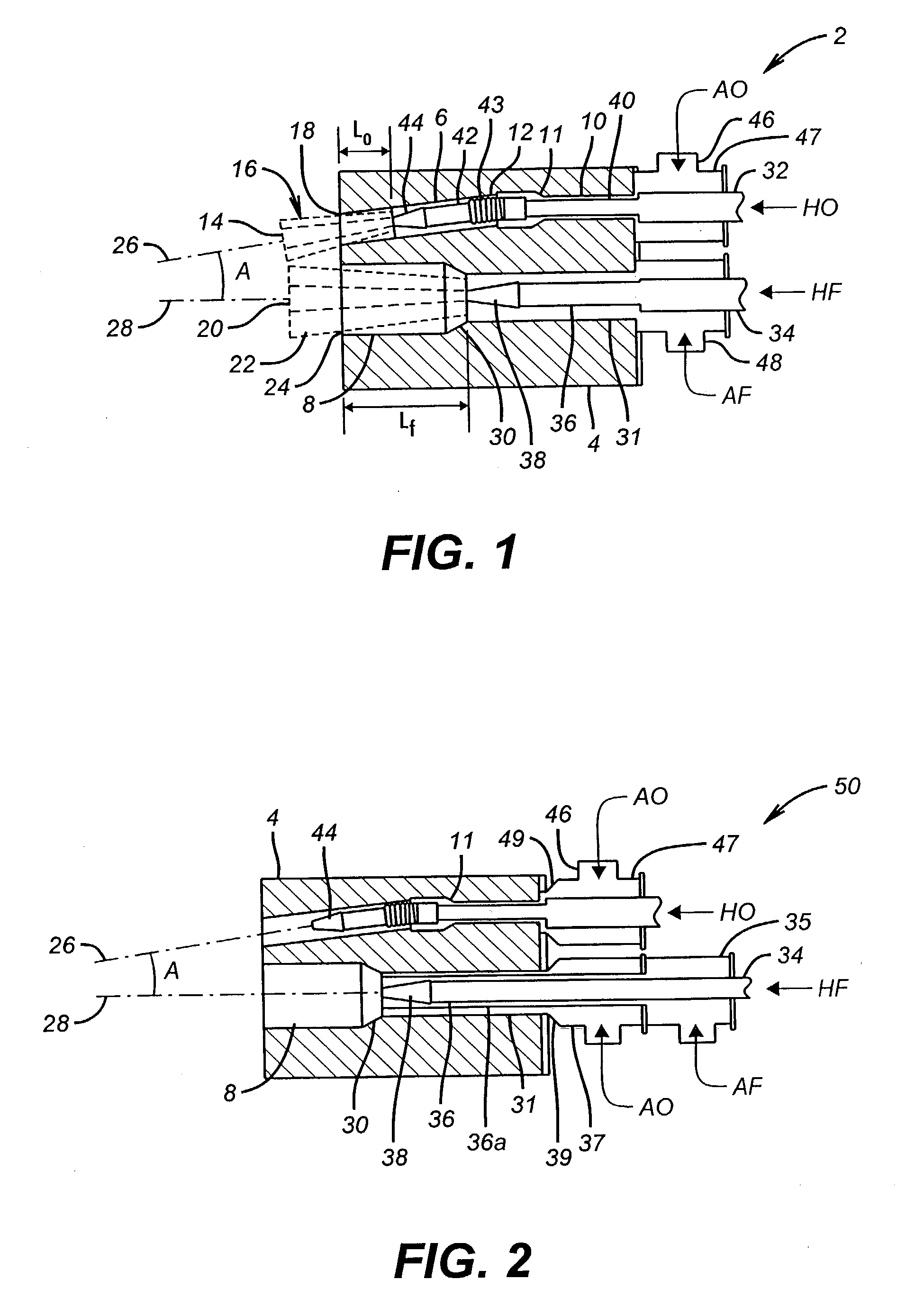
[0056] FIG. 1 illustrates many of the features of the burner apparatus of the present invention. Illustrated at 2 is the burner apparatus, having a refractory burner block 4. Refractory burner block 4 comprises an upper cavity 6 which serves as the cavity through which ambient oxidant, designed as "AO", passes through on its way toward the furnace. Cavity 8 (illustrated in the lower portion of the refractory burner block) entails a passage through which ambient fuel (designated as "AF") passes as indicated by the arrow in FIG. 1. A first portion of cavity 6 is shown at 10 having a diameter, which is an initial diameter smaller than the rest of cavity 6. An expansion section at 11 is also indicated which transitions the smaller diameter section 10 into the main portion of cavity 6. The larger diameter section is designated 12 in FIG. 1. Preheated oxidant (indicated as "HO" in FIG. 1) is illustrated emanating on the left-hand side of the burner block at 14, while ambient oxidant emana...

third embodiment

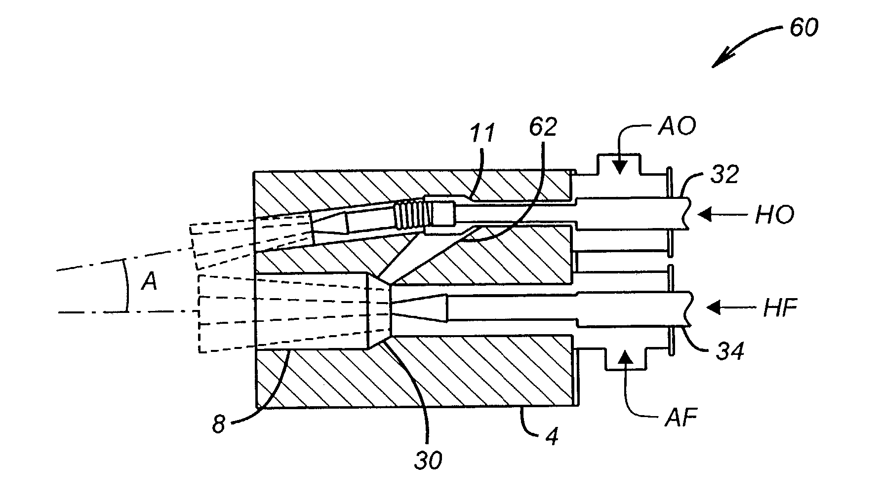
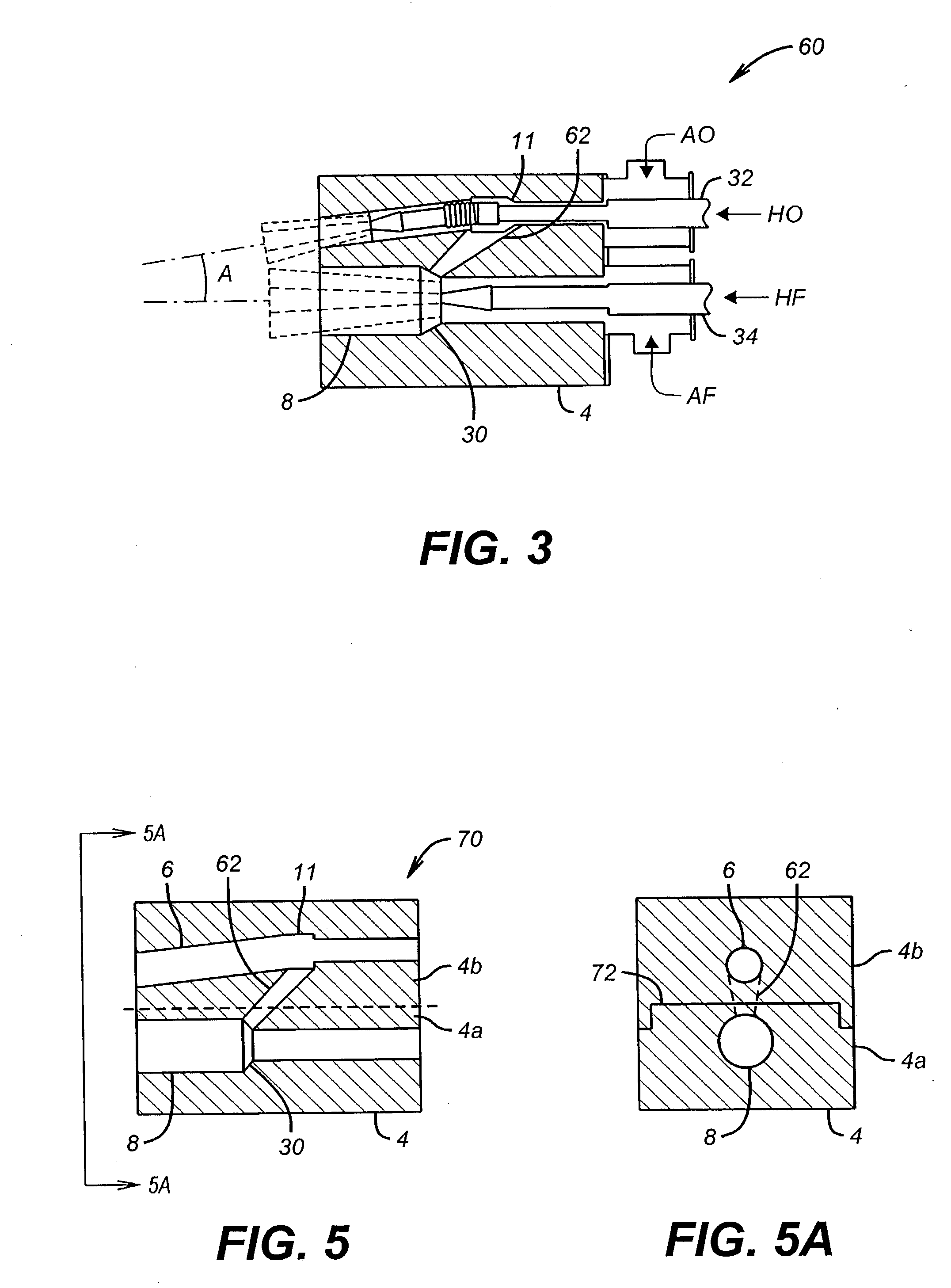
[0062] FIG. 3 illustrates the inventive burner apparatus. This embodiment is designated as 60 in FIG. 3, and includes the provision of a connecting passage 62 which connects the ambient oxidant cavity 11 with the ambient fuel cavity 8 near the position of the expansion section 30. All other respects the embodiment of FIG. 3 is the same as the embodiment to FIG. 1. The provision of connection 62 allows certain advantages, as will be further explained herein.

[0063] FIGS. 4 and 4A illustrate another embodiment of a burner apparatus in accordance with the invention. Burner apparatus 80 includes a refractory burner block 4, having a plurality of ambient oxidant cavities indicated at 81a, b, and c, all feeding a slot 82, and an ambient fuel cavity indicated at 86. The ambient oxidant enters the refractory burner block 4 in a first diameter cavity 81 that is narrower in diameter than cavity 82. This allows some expansion of the ambient oxidant and the heated oxidant, the preheated oxidant ...

embodiment 70

[0064] FIG. 5 indicates another preferred embodiment of the burner apparatus in accordance with the present invention. In this embodiment 70, refractory burner block 4 comprises a lower half 4a and an upper half 4b as indicated in FIGS. 5 and 5A. This design allows for the connection 62 to be more easily provided for. As illustrated in FIG. 5A, lower half 4a and upper half 4b of refractory burner block 4 are fit together along a sliding channel 72 which provides a tight fit between the upper and lower blocks. Connection 62 is generally shown as having greater diameter near the connection with the cavity adapted to convey ambient oxidant 6, and having a smaller diameter near the connection to the cavity adapted to convey preheated fuel 8. While this is not necessary for operation of the burner of this embodiment, this configuration provides an ejector-type action as will be further explained herein. The preheated oxidant and preheated fuel conduits are not shown in the embodiment ill...


PUM


Abstract

A burner apparatus comprises a conduit adapted to convey preheated oxidant and having outlet and inlet ends, and a conduit adapted to convey preheated fuel and having outlet and inlet ends. The conduit adapted to convey preheated fuel is substantially parallel to the conduit adapted to convey preheated oxidant. The conduit adapted to convey preheated oxidant is positioned substantially vertically above the conduit adapted to convey preheated fuel. The conduit adapted to convey preheated oxidant and the conduit adapted to convey preheated fuel each are positioned within its own respective elongate cavity in a refractory burner block. Each of the conduits are positioned in their respective cavity such that a substantially annular region is present between an outer surface of each conduit and its respective cavity. Each conduit inlet end extends through a respective plenum for receiving an ambient temperature fluid, the plenums adapted to pass the ambient temperature fluid into the respective annular regions.

Description

[0001] 1. Field of the Invention[0002] The invention relates to apparatus for combusting preheated fuel and / or preheated oxidant.[0003] 2. Related Art[0004] There are three basic types of combustion systems based on temperature of the fuel and oxidant: First and most common burner system utilize unheated (or ambient) fuel and oxidant for combustion. Both air-fuel and oxy-fuel burners of above types are widely used in industry (see U.S. Pat. Nos. 5,199,866; 4,690,635).[0005] The second type of burner system employs preheating the ambient fluids (fuel and oxidant) inside the burner embodiment. This method employs ambient or slightly preheated fuel and oxidant as an input to the burner. It is commonly used with air-fuel burners and combustion engines. U.S. Pat. No. 4,257,762 describes one such method where preheated forced draft air is used for preheating fuel gas by partial mixing in the burner passage. In another application (U.S. Pat. No. 5,413,477), hot flue gas is entrained inside...

Claims


Application Information

Patent Timeline
Patent Type & Authority Applications(United States)
IPC IPC(8): F23C7/00F23D11/38F23D14/22F23D14/32F23D14/48F23D14/66F23M5/02
CPCF23C7/002F23D14/22F23D14/32Y02E20/344F23D2212/10F23D2212/20F23M5/025F23D14/66Y02E20/34
Inventor JOSHI, MAHENDRA L.FOSSEN, ARNAUDBORDERS, HARLEY A.TSIAVA, REMI P.CHARON, OLIVIER
Owner LAIR LIQUIDE SA POUR LETUDE & LEXPLOITATION DES PROCEDES GEORGES CLAUDE
Why Eureka
Try Eureka