Acoustical noise reducing enclosure for electrical and electronic devices

Inactive Publication Date: 2003-08-21
SCS HLDG LLC
View PDF7 Cites 5 Cited by
  • Summary
  • Abstract
  • Description
  • Claims
  • Application Information

AI Technical Summary

Benefits of technology

0007] The primary objects of the invention are to provide means for reducing and controlling noise generated by electronic equipment hou

Problems solved by technology

A separate room generally requires extra personnel to load and operate the recorders while same room operation is a generally a substantial compromise in

Method used


Image

  • Acoustical noise reducing enclosure for electrical and electronic devices
  • Acoustical noise reducing enclosure for electrical and electronic devices
  • Acoustical noise reducing enclosure for electrical and electronic devices

Examples


Embodiment Construction

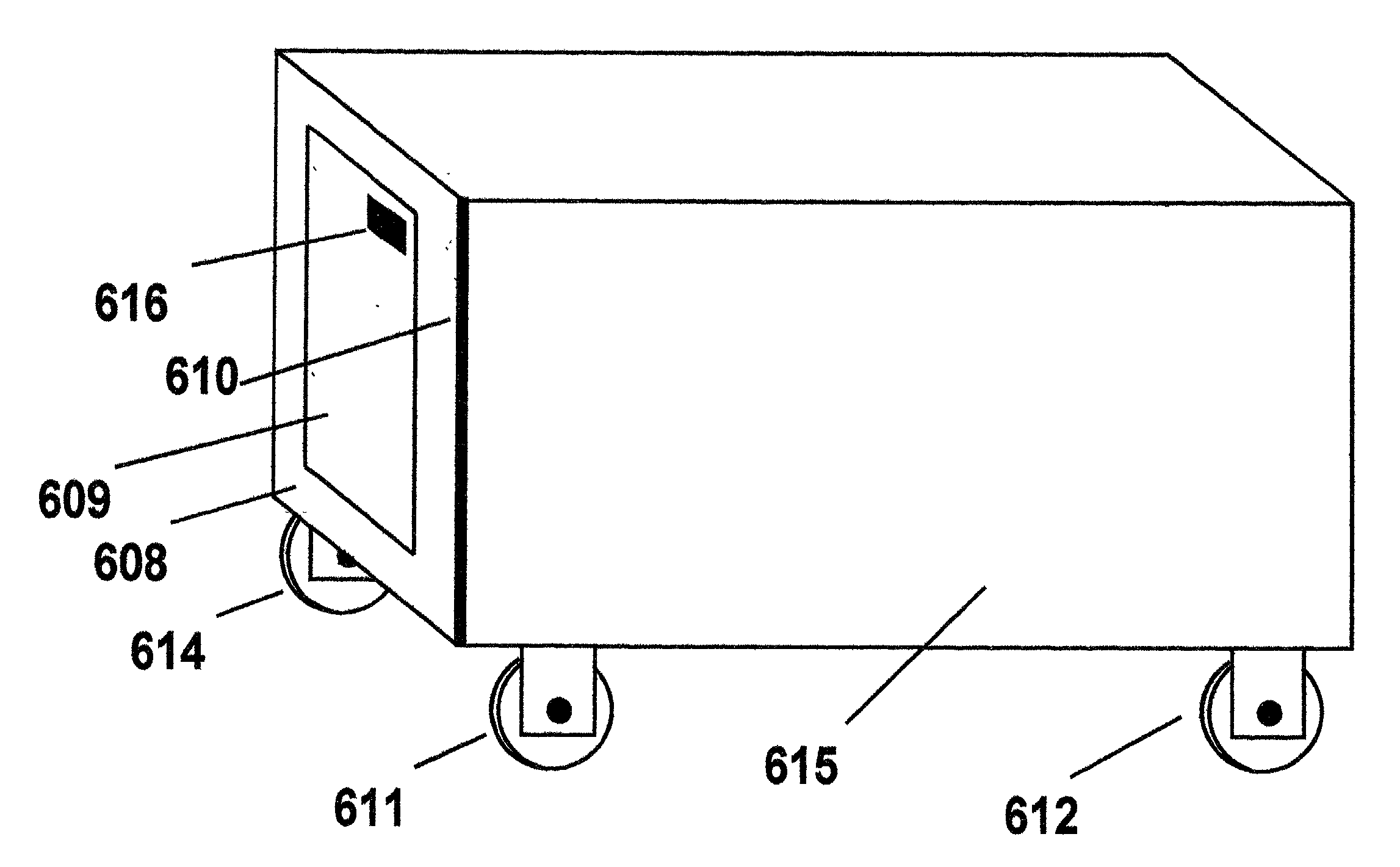
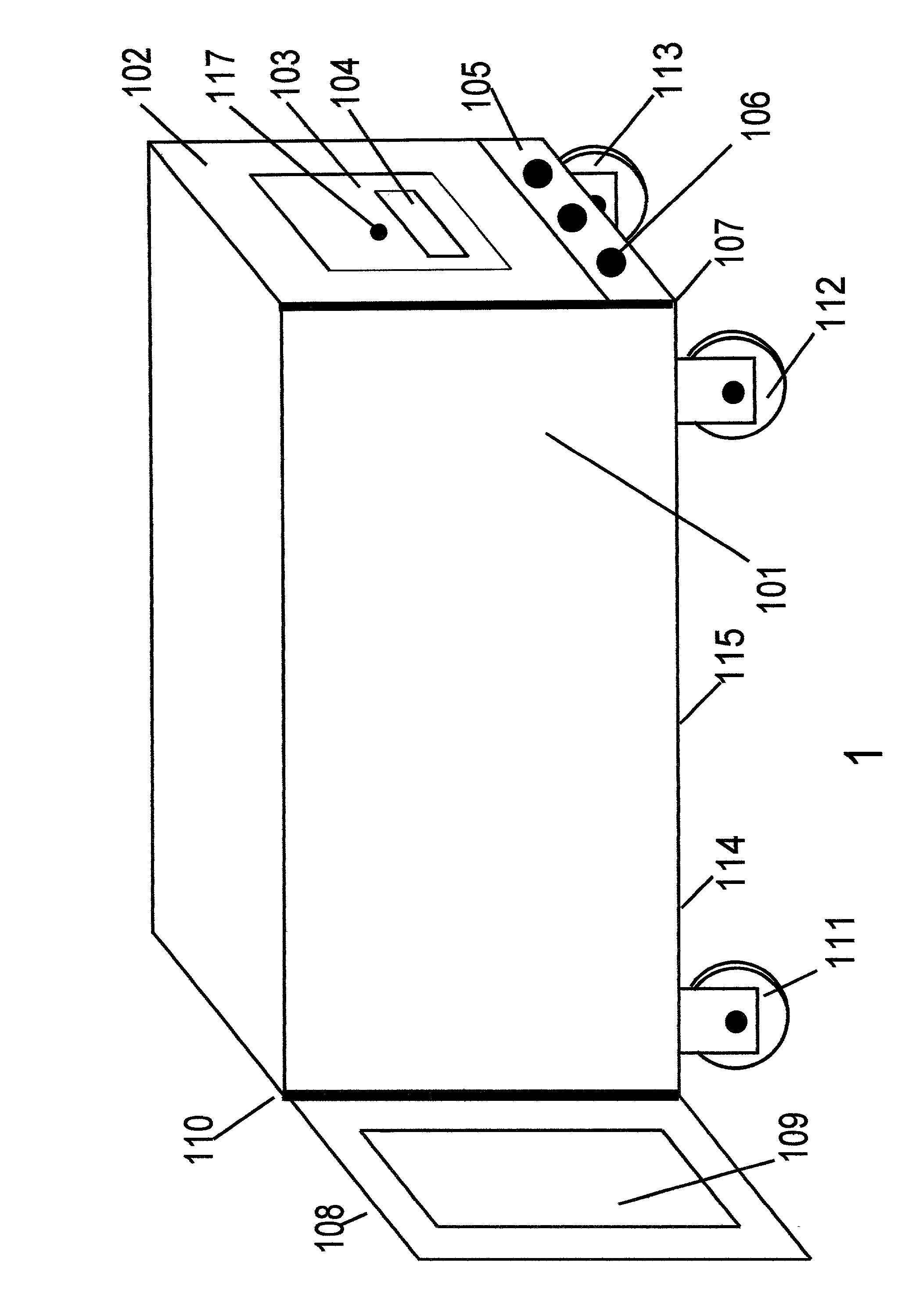
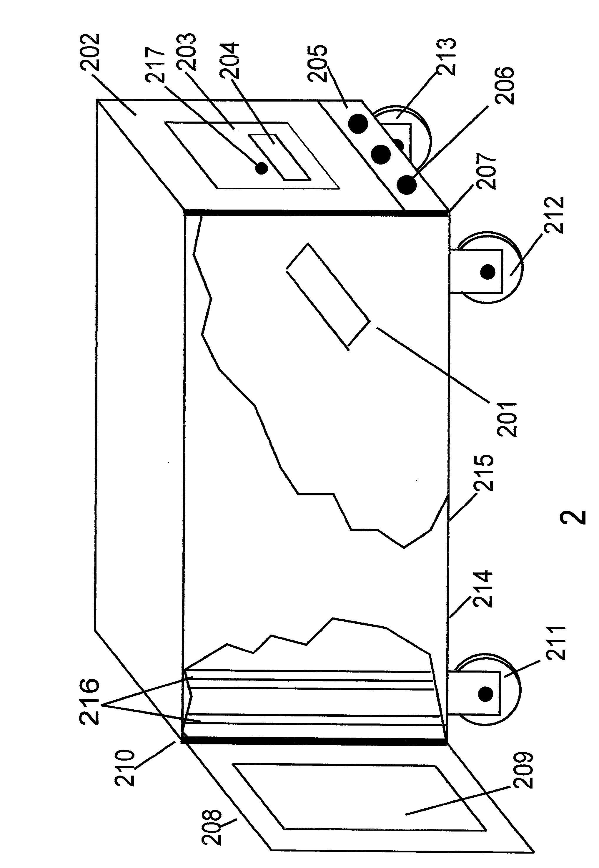
[0039] The cabinet 111 in the preferred embodiment has a height of 24.75 inches, a depth of 33 inches, and a width of 22.5 inches and is made of plywood or medium density fiber-board. It will house equipment with a maximum height of 21 inches or 12 rack units with a maximum equipment depth of 24 inches. The interior walls are lined with reticulated foam for sound absorption and the air intake port 201 has an electrostatic filter 702 fitted to it to minimize dust being sucked into the cabinet. Mounted above the air intake port 202 is a sheet of acoustic absorption material 701, such as Owens-Corning 703, which is larger than the port opening to reduce sound transmission out of that port.

[0040] Equipment is mounted in the cabinet on rails 216 located behind and to the left and right of the front door. These rails are mounted to the cabinet on vibration absorbers such as those manufactured by Sorbothane.

[0041] The exhaust / sound trap assembly 203 uses two 4.5 inch boxer fans operated at...


PUM


Abstract

The invention disclosed herein is a system for controlling acoustical noise generated by electrical or electronic equipment. The invention consists of a sealed enclosure having acoustically absorbent inner walls, a transparent sealed front door, a hinged sealed rear access panel to facilitate equipment wiring and installation and a high volume/low pressure air cooling system and additional sound and vibration absorption elements. Means for monitoring and controlling internal cabinet temperature and sealed electrical ports for interfacing the equipment housed within the enclosure to the outside while substantially reducing acoustical noise generated by that equipment.

Description

[0001] This invention relates to electronic equipment cabinets, to the control of noise generated by electromechanical equipment and to the cooling of enclosed electronic equipment.[0002] Electrical and electronic equipment cabinets have been built since the late 1800's. Serviceability, access to internal components and internal heat management and control have been issues in their design for almost as long, but the need to control noise generated by internal components is a relatively new development driven by the use of equipment in sound and video recording and editing which needs to be located physically near the user.[0003] Earlier methods to control mechanical noise generated by such devices were accomplished by placing those devices in separate rooms that were acoustically isolated from the user or in separate areas of the same room treated with sound absorbing materials. A separate room generally requires extra personnel to load and operate the recorders while same room oper...

Claims


Application Information

Patent Timeline
IPC IPC(8): H05K7/20
CPCH05K7/20136
Inventor BEETEN, TODD W.
Owner SCS HLDG LLC
Why Eureka
Try Eureka