Waveguide architecture, waveguide devices for laser processing and beam control, and laser processing applications

a waveguide and laser processing technology, applied in lasers, gas laser construction details, lasers, etc., can solve the problems of high cost of laser diodes, fiber lasers offer good power scalability but limited at high power, and it is difficult to achieve the requirements of rods, slabs, and thin disk lasers

Inactive Publication Date: 2003-08-28
GSI LUMONICS LTD
View PDF31 Cites 119 Cited by
  • Summary
  • Abstract
  • Description
  • Claims
  • Application Information

AI Technical Summary

Problems solved by technology

When compared to lamp-pumped, solid state lasers, LPL's, diode-pumped, solid state lasers, DPL's, offer significant advantages in terms of beam quality, efficiency, and reliability, but their cost effectiveness is hampered by the high cost of laser diodes.
Fiber lasers offer good power scalability but are limited at high power as a result of non-linear interactions in the gain medium, which is often several meters in length.
It is generally difficult to achieve the requirements with rods, slabs, and thin disk lasers.
The transverse gradients, though relatively small, can be large enough to produce undesirable lens effects, particularly in a side pumped arrangement.
The Pockels cells require Kilovolt level signals for on-off switching and acousto-optic modulators are often limited by acoustic transit time.
For instance, the device may be non-uniformly cooled on both faces to improve the stability or to produce a desired output mode.
However, various other dielectric materials, for instance Silicon Dioxide, require much higher fluence.

Method used


Image

  • Waveguide architecture, waveguide devices for laser processing and beam control, and laser processing applications
  • Waveguide architecture, waveguide devices for laser processing and beam control, and laser processing applications
  • Waveguide architecture, waveguide devices for laser processing and beam control, and laser processing applications

Examples


second embodiment

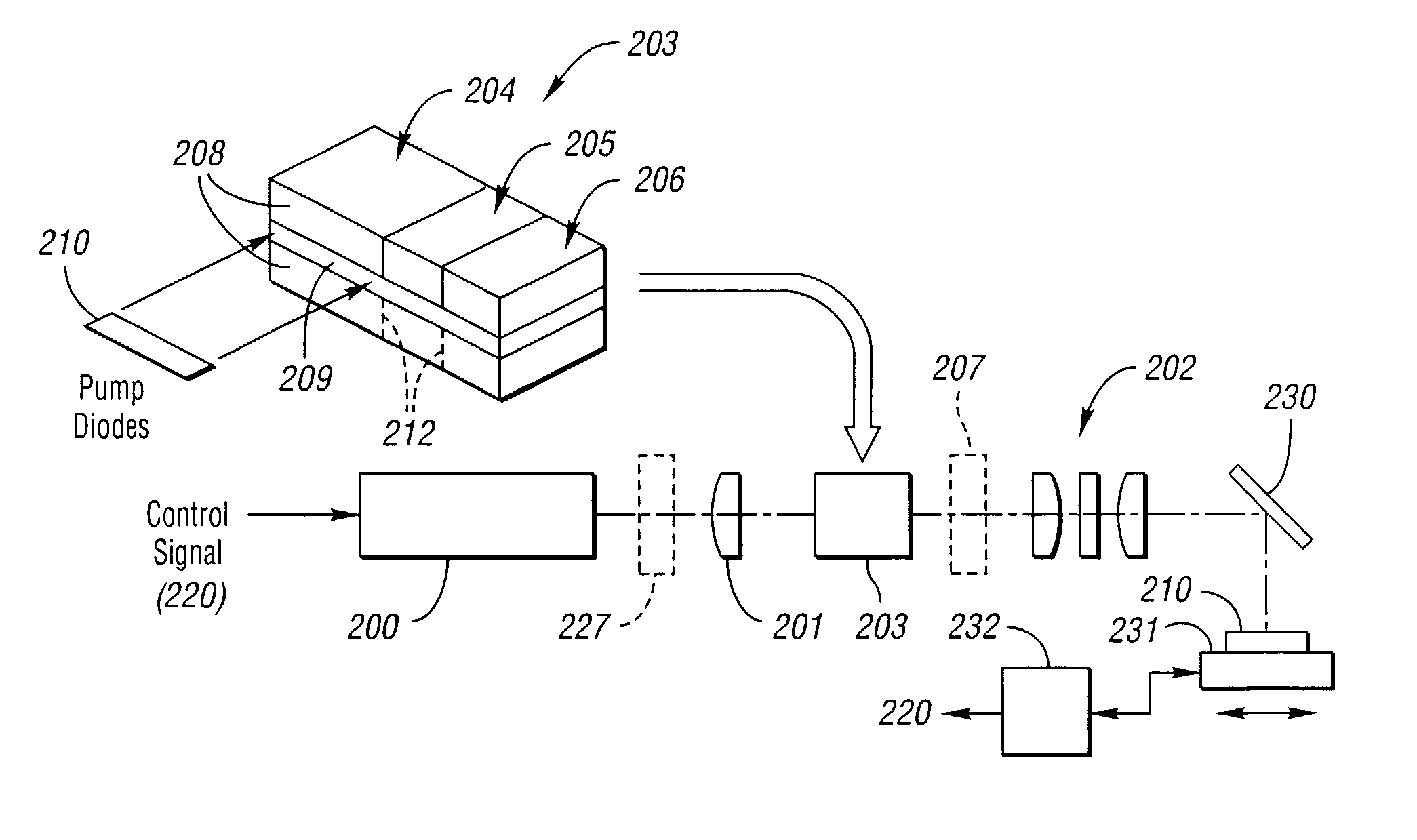
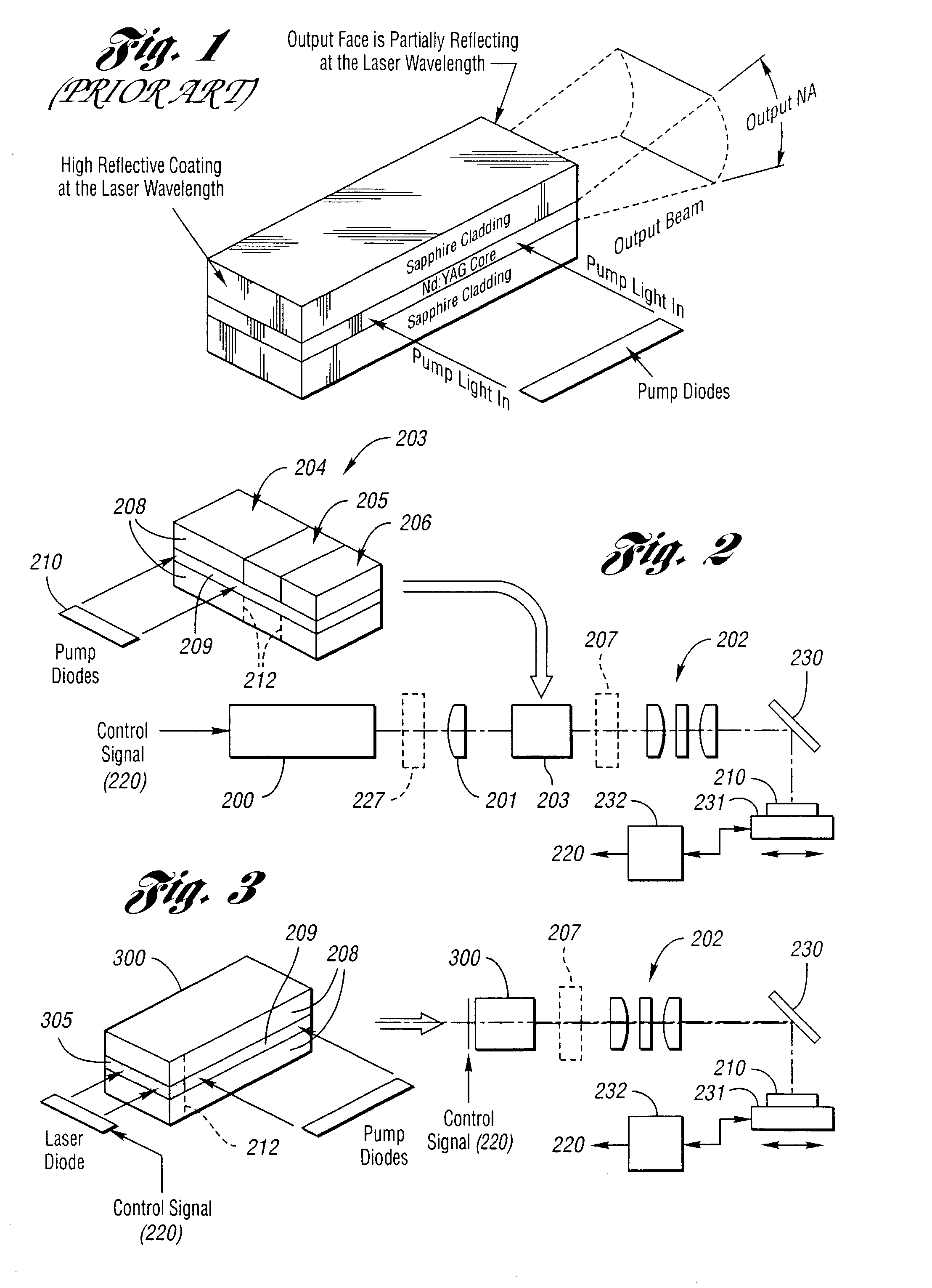
[0126] In an alternative embodiment, top 708 and side 709 views which are shown in FIGS. 7D and 7E, the planar waveguide is configured to make at least one fold 710 in the transverse direction and the birefringent cladding 711 is contacted / bonded to a side face of the planar waveguide structure where the beam is reflected to create a fold. In this second embodiment if the birefringent cladding is a uniaxial crystal and the angle of incidence at the fold is .THETA..sub.1, then the refractive indices of the birefringent cladding should satisfy n.sub.o

[0127] Preferably, the polarizer is integrated directly into a monolithic device which may have separate gain and polarization sections. However, the waveguide polarizer may be used to produce a polarized output beam wherein an input beam is coupled into the core with an imaging system, for example.

[0128] It is to be understood tha...

first embodiment

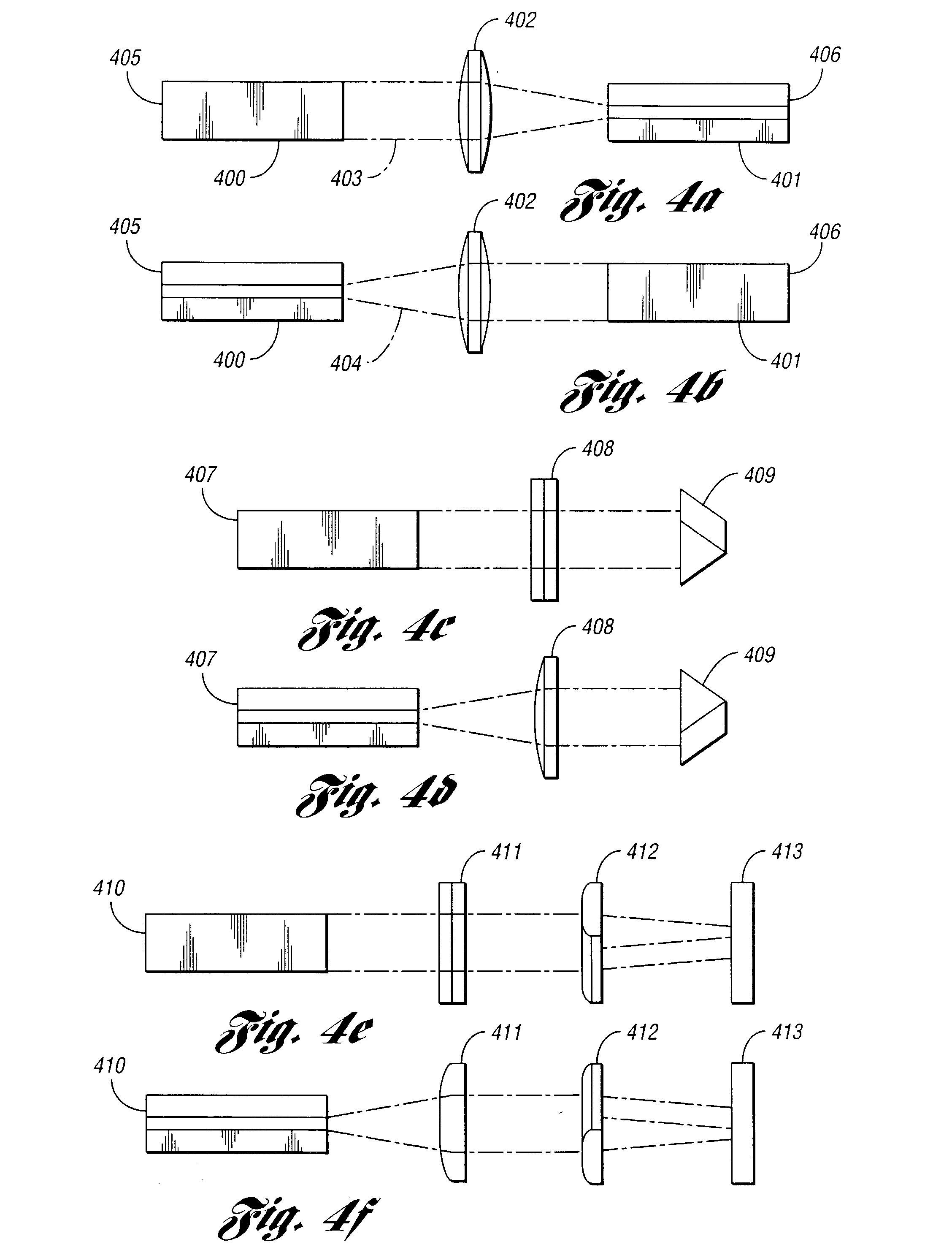
[0157] Refer to FIG. 9-A. In a first embodiment, an electro-optic waveguide with transverse electrodes is formed by building a sandwich of three layers 901, 902, 903 of an electro-optic material such as Lithium Niobate, LiNbO.sub.3. The thickness of the central core layer 902 is typically in the range of 5-200 microns. The outer cladding layers 901, 903 have a typical thickness in the range of 5-50 microns. The width and length of the device are application dependent. All three layers have their crystal optical axis 925 (the +z axis) parallel to the direction of propagation in the waveguide. The outer two layers have their +x and +y crystal axes oriented in the same direction. The +x and +y crystal axes of the central layer are rotated 180.degree. about the +z axis relative to the outer two layers. Electrodes are created on the top and bottom surfaces of the structure 904 by coating them with an electrically conducting coating or by contacting electrically conducting materials to th...


PUM

PropertyMeasurementUnit
lengthaaaaaaaaaa
lengthaaaaaaaaaa
Wavelengthaaaaaaaaaa

Abstract

Methods and systems for laser-based processing of materials are disclosed wherein a scalable laser architecture, based on planar waveguide technology, provides for pulsed laser micromachining applications while supporting higher average power applications like laser welding and cutting. Various embodiments relate to improvements in planar waveguide technology which provide for stable operation at high powers with a reduction in spurious outputs and thermal effects. At least one embodiment provides for micromachining with pulsewidths in the range of femtoseconds to nanoseconds. In another embodiment, 100W or greater average output power operation is provided for with a diode-pumped, planar waveguide architecture.

Description

[0001] This application is a continuation in part of co-pending U.S. patent application Ser. No. 09 / 912,214 entitled "Waveguide Laser with Mode Control and Pump Light Confinement", filed Jul. 24, 2001. The co-pending '214 application is assigned to the assignee of the present invention with a common inventor. The entire disclosure of Ser. No. 09 / 912,214 is hereby incorporated by reference in its entirety. This application also claims the benefit of U.S. Provisional patent application Serial No. 60 / 338,125 entitled "Pumping Architecture for Waveguide Lasers", filed Nov. 13, 2001. This application is also related to co-pending U.S. Ser. No. ______, entitled "Laser Processing Method and System", filed the same day as the present application.[0002] 1. Field of the Invention[0003] The present invention generally relates to pumped solid-state lasers, amplifiers, and laser processing devices and methods for using same and, particularly, when such pumping is provided by one or more laser di...

Claims


Application Information

Patent Timeline
Patent Type & Authority Applications(United States)
IPC IPC(8): H01S3/06H01S3/063H01S3/0941
CPCH01S3/08095H01S3/08059H01S3/094084H01S3/0941H01S3/09415H01S3/113H01S3/2308H01S3/2325B23K26/063B23K26/0635B23K26/0648B23K26/0652B23K26/0732B23K26/365B23K26/4065H01S3/0405H01S3/06H01S3/0606H01S3/061H01S3/0612H01S3/0615H01S3/0627H01S3/063H01S3/08H01S3/0818B23K26/0622B23K26/0624B23K26/361B23K2103/42B23K2103/50H01S3/083H01S3/1643
Inventor FILGAS, DAVID M.HARAN, FRANKMANK, ANDREASROBERTSON, JOHN
Owner GSI LUMONICS LTD
Why Eureka
Try Eureka