

Elliptically polarizing plate and liquid crystal display
a technology of elliptically polarizing plates and liquid crystal displays, which is applied in the direction of polarizing elements, instruments, optics, etc., can solve the problems of deterioration in display quality, theoretically inappropriate compensation, and the ability to obtain practically unfavorable liquid crystals
Inactive Publication Date: 2003-09-04
KENT STATE UNIV +1
View PDF3 Cites 20 Cited by
- Summary
- Abstract
- Description
- Claims
- Application Information
AI Technical Summary
Benefits of technology
[0030] A liquid crystal display having a wide viewing angle can be realized applying an elliptically polarizing plate comprises a polarizer, a first optical anisotropic layer having positive refractive index, and having an optical axis which is tilted with respect to the plane of the polarizer and a second optical anisotropic layer having negative refractive index, and an optical axis which is tilted with respect to the plane of the polarizer. Namely a liquid crystal display having a sufficient display contrast in a viewing angle direction in all azimuth and having a characteristic such that a change in display color from the front is small when the viewing angle is changed, by using an elliptically polarizing plate. In particular, a liquid crystal display having a more sufficient in a viewing properties can be realized applying an other elliptically polarizing plate having a different optical anisotropic layer from said elliptically polarizing plate is configured on opposite side of the liquid crystal cell.
Problems solved by technology
As a consequence, it is theoretically inappropriate to compensate for the orientation state in which an optical axis of the rod-like nematic liquid crystal cell has a tilt approximate to the normal line direction with respect to the cell surface in the black state.
Thus, only a practically unfavorable liquid crystal can be obtained.
However, the colorization phenomenon is conspicuous when the viewing angle in the white display is changed so that the problem of the deterioration in the display quality cannot be solved.
However, no retardation film is observed in which the total viewing angle properties such as a display contrast and the colorization are not remarkably improved with accurate retardation compensation.
Method used
View moreImage
Smart ImageViewing Examples

Examples
example 1 to 5
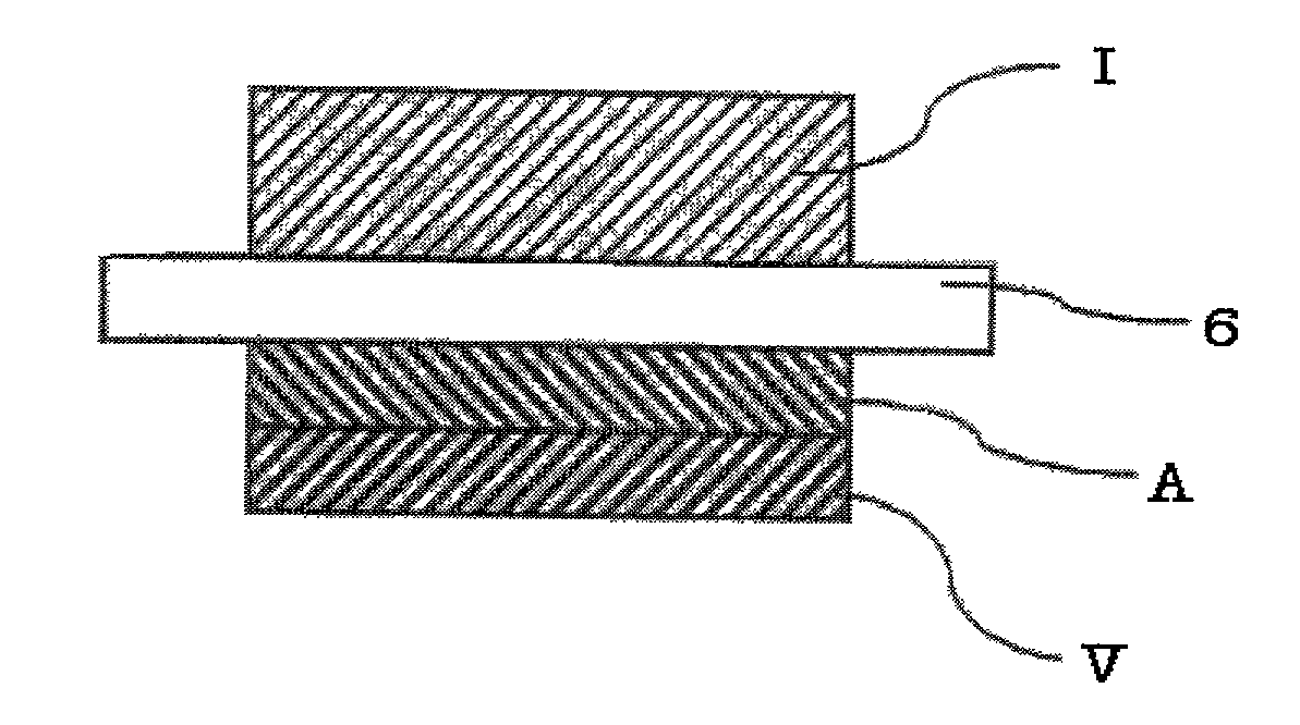
[0094] The NH film was laminated to the polarizing plate so that the polarizing transparent axis and the optical axis tilt direction orthgonally with each other via an acryl series pressure sensitive adhesive. Furthermore, a WV film was laminated on the NH film so that the optical axis tilt directions of the NH film and the WV film orthgonally with each other with the result that an elliptically polarizing plate (I) was provided.
Login to View More PUM
| Property | Measurement | Unit |
|---|---|---|
| tilt angle | aaaaa | aaaaa |
| thickness | aaaaa | aaaaa |
| thickness | aaaaa | aaaaa |
Abstract
An elliptically polarizing plate, comprising a polarizer, a first optical anisotropic layer having positive refractive index anisotropy and an optical axis of the anisotropy that is tilted, and a second optical anisotropic layer having negative refractive index anisotropy and an optical axis that is tilted, have accurate retardation compensation of a liquid crystal cell, and the liquid crystal display maintains a display contrast having a sufficient visibility when the viewing angle is changed and which does not generate colorization.
Description
[0001] 1. Field of the Invention[0002] The present invention relates to an elliptically polarizing plate and a liquid crystal display (LCD), which maintains a sufficient display contrast in all azimuths and which has a display performance that does not generate a color shift.[0003] 2. Description of the Prior Art[0004] Currently, a mainstream method of a general liquid crystal display is a thin-film transistor (TFT) LCD using a twisted nematic (TN) liquid crystal. In this method, there is available an advantage in that a response speed is high, and a high contrast can be obtained. However, when a display panel using a TN liquid crystal is seen from a tilt angle to direction of a normal line, the contrast is remarkably lowered, and a gray scale reversion is generated in which the gray scale display is reversed. The display panel has a characteristic such that a viewing angle is extremely narrow. In the usage of a large-scale monitor and a television or the like, a high contrast, a wi...
Claims
Login to View More Application Information
Patent Timeline
 Patent Type & AuthorityApplications(United States)
IPC IPC(8): G02F1/1335G02F1/13363G02B5/30
CPCG02F1/133528G02F1/13363G02F2413/10G02F2413/02G02F2202/40G02B5/30
InventorKELLY, JACKSERGAN, TATIANALAVRENTOVICH, MARINANISHIKOUJI, YUUICHIKAMEYAMA, TADAYUKI
OwnerKENT STATE UNIV