Method and device for determining a speed parameter of at least one powered wheel pertaining to a vehicle

a technology speed parameter, which is applied in the direction of process and machine control, tractors, instruments, etc., can solve the problems of systemic error, inability to determine the speed parameter of at least one powered wheel, and inability to accurately describe the vehicular speed

Inactive Publication Date: 2003-09-04
ROBERT BOSCH GMBH
View PDF6 Cites 17 Cited by
  • Summary
  • Abstract
  • Description
  • Claims
  • Application Information

AI Technical Summary

Benefits of technology

[0015] With the aid of the method of the present invention, an equivalent quantity can be formed for a wheel speed or wheel rotational speed not directly available. For example, a directly determined variable is not available when a wheel-speed sensor is defective. Thus, using the method of the present invention, a reliable speed variable of the wheel can be made available in spite of the failure of a wheel-speed sensor. The system availability of a motor vehicle is thereby increased, particularly in the event of a wheel-speed sensor malfunction. That is to say, the vehicle continues to be operable in spite of the failure or defect of a wheel-speed sensor. In particular, a reliable quantity describing the speed variable of the wheel can be made available to a traction control system or a vehicle-dynamics control system of a motor vehicle in spite of a malfunction of a wheel-speed sensor. In comparison to previously used traction control systems or vehicle-dynamics control systems, when using the method of the present invention, a system need no longer be switched into the passive state in response to a detected fault in a wheel-speed sensor. The system continues to be available and fully operative, in spite of such a fault or failure of the wheel-speed sensor.

Problems solved by technology

The ascertainment of the wheel speed known from DE 196 108 64 A1 has the disadvantage that a variable describing the vehicular speed is necessary.
This demands either very accurate estimation methods which determine the vehicular speed, for example, on the basis of the wheel speeds, or else special sensors for detecting the wheel speeds, which, however, require too much effort and are therefore costly.
Because of this, a systematic error can possibly develop, since a further variable which is independent of the wheel speeds does not go into the determination of the rotational speeds.
For example, a directly determined variable is not available when a wheel-speed sensor is defective.

Method used


Image

  • Method and device for determining a speed parameter of at least one powered wheel pertaining to a vehicle
  • Method and device for determining a speed parameter of at least one powered wheel pertaining to a vehicle
  • Method and device for determining a speed parameter of at least one powered wheel pertaining to a vehicle

Examples


Embodiment Construction

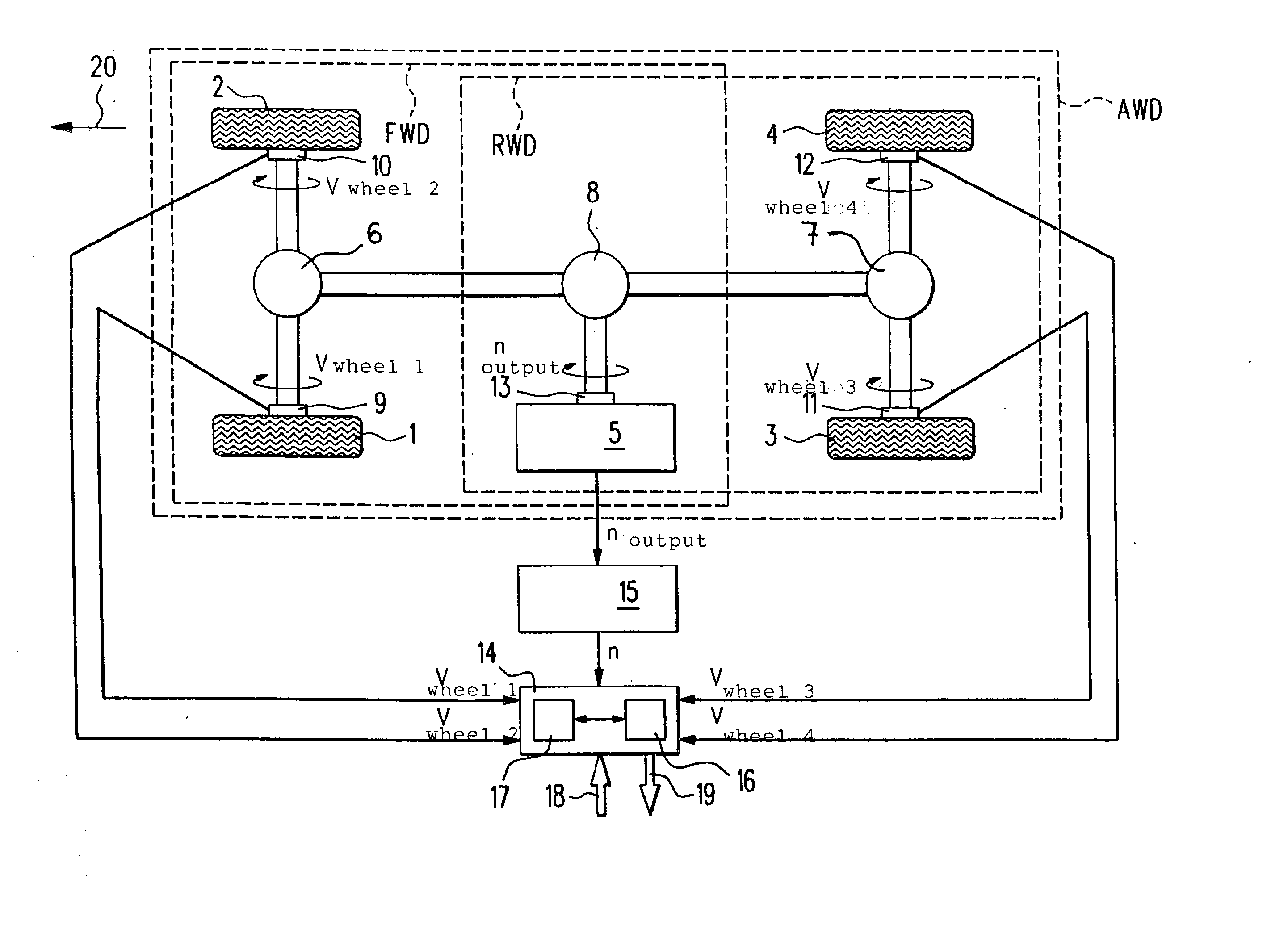
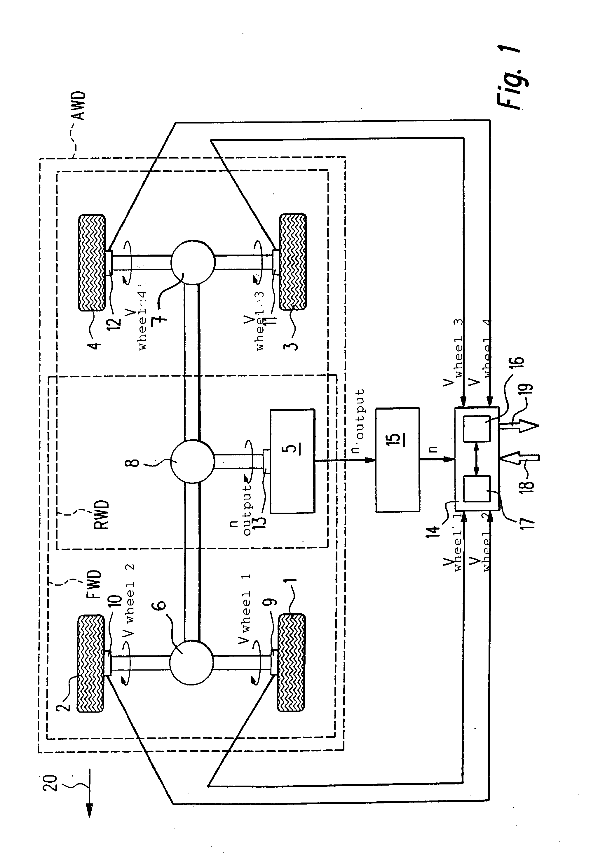
[0033] FIG. 1 shows a drive train of a motor vehicle having four wheels 1, 2, 3, 4. The direction of travel of the motor vehicle is indicated by an arrow 20. The front wheels (front-wheel drive, FWD), the rear wheels (rear-wheel drive, RWD) or the front and rear wheels (all-wheel drive, AWD) can be driven in the motor vehicle. The driven wheels of the FWD and of the RWD are generally fixedly coupled via a differential to the output end of a transmission 5. In the case of AWD, there is a fixed coupling only when no lm slip-encumbered components, such as a viscous-friction coupling (so-called viscous coupling) are integrated into this part of the drive train. This fixed coupling exists in the case of all-wheel-drive vehicles with open differentials. As can be seen in FIG. 1, the single-axle-driven motor vehicles, i.e. FWD and RWD motor vehicles, have two differentials 6, 7. All-wheel drive, i.e. AWD vehicles, have three differentials 6, 7, 8.

[0034] Both front wheels 1, 2 of the vehicl...


PUM


Abstract

The invention relates to a method and a device for determining a variable describing the speed (VwheelDef)of at least one driven wheel (1, 2, 3, 4) of a motor vehicle. In this context, variables describing the respective wheel speeds (Vwheeli)for the remaining driven wheels of the motor vehicle, and a variable describing the output rpm (noutput) of a transmission (5) of the motor vehicle are determined. To be able to make a reliable variable describing the speed magnitude of the wheel (1, 2, 3, 4) available to a traction control system or a vehicle-dynamics control system of a motor vehicle in spite of the failure of a speed sensor (9, 10, 11, 12) arranged at one of the wheels, it is proposed that the variable describing the speed (VwheelDef) for the at least one driven wheel (1, 2, 3, 4) be determined as a function of the variables which describe the respective wheel speeds (Vwheeli) of the remaining driven wheels and as a function of the variable which describes the transmission output rpm (noutput).

Description

BACKGROUND INFORMATION[0001] The present invention relates to a method and a device for determining a variable which describes the speed of at least one driven wheel of a motor vehicle. Using the method and the device, variables which describe the respective wheel speeds are ascertained for the remaining driven wheels of the motor vehicle. Furthermore, a variable is determined which describes the output rpm of a transmission of the motor vehicle.[0002] The invention also relates to a control unit for a traction control system or a vehicle-dynamics control system of a motor vehicle. To control the drive slip and / or the vehicle dynamics, the control unit determines a variable which describes the speed of at least one driven wheel of the motor vehicle. Variables describing the respective wheel speeds for the remaining driven wheels of the motor vehicle, and a variable describing the output rpm of a transmission of the motor vehicle are available to the control unit.[0003] Furthermore, ...

Claims


Application Information

Patent Timeline
Patent Type & Authority Applications(United States)
IPC IPC(8): B60T8/17G01P3/50B60T8/172B60T8/175B60T8/1755B60T8/66B60T8/88
CPCB60T8/172B60T8/885B60T2210/16Y10T477/679B60T2270/202B60T2270/416B60T2250/042B60T8/00
Inventor ERBAN, ANDREAS
Owner ROBERT BOSCH GMBH
Why Eureka
Try Eureka