Gas sensor calibration system

a calibration system and gas sensor technology, applied in the calibration of gas analysers, instruments, chemical methods analysis, etc., can solve the problems of expensive, time-consuming, frequent non-compliance, etc., and achieve the effect of less wasteful calibration gas and less wasteful

Inactive Publication Date: 2003-09-11
ZELLWEGER ANALYTICS
View PDF9 Cites 20 Cited by
  • Summary
  • Abstract
  • Description
  • Claims
  • Application Information

AI Technical Summary

Benefits of technology

[0012] The source of pressurised calibration gas may contain only enough calibration gas for a single calibration operation, i.e. the source provides a single "shot" calibration gas. Alternatively, the source may be a bottle containing more than one dose, in which case the apparatus further includes a metering device for delivering a metered dose of calibration to the interface. Both these arrangements are quicker, easier, safer and less wasteful of calibration gas than-the prior art arrangement and accordingly stand a better chance of being used on each occasion that the detector is used in a potentially hazardous space than the prior art arrangement described above. Because the arrangement of the present invention is much less wasteful of calibration gas, it is also more economic than the prior art arrangement.

Problems solved by technology

Safety regulations require that the sensors within the detector are tested on each occasion that they are taken into a potentially hazardous environment and calibrated according to manufacturer's recommendations and that is indeed good commercial practice but it is frequently not complied with for reasons of cost and time.
Calibration gas flowing out of the conduit is vented to atmosphere and so the procedure is wasteful of calibration gas, which is expensive.
In addition, the gas flow rate in the conduit must be adjusted and controlled to pre-set levels, which is time consuming.
The gas required for calibration could be hazardous and if so, calibration should be carried out in a controlled environment.
However, portable gas monitors that work by diffusion of the monitored gas into the monitor have no flow path past the sensor.

Method used


Image

  • Gas sensor calibration system
  • Gas sensor calibration system
  • Gas sensor calibration system

Examples


Embodiment Construction

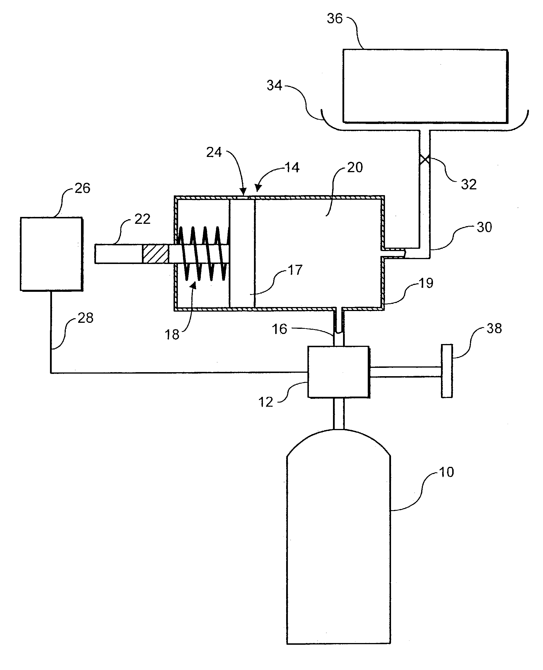
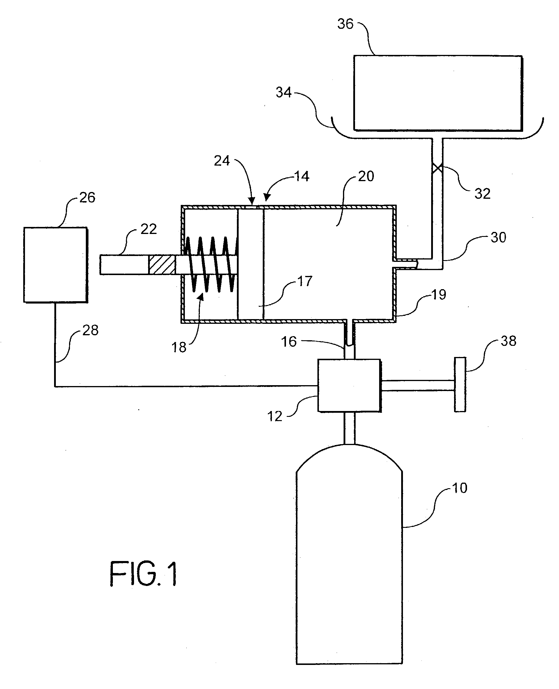
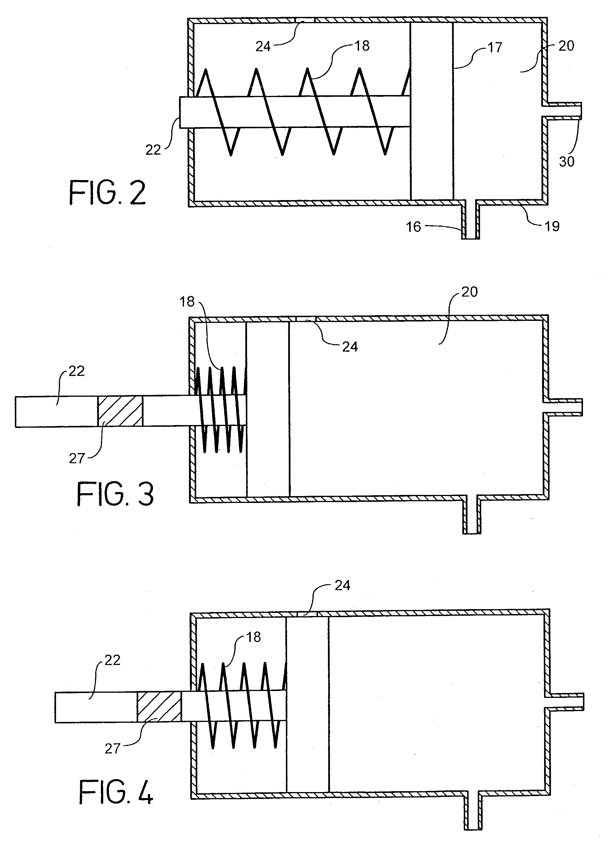
[0019] Referring initially to FIG. 1, a gas bottle 10 containing enough pressurised calibration gas for several gas detector calibrations is connected to a control valve 12, e.g. by way of a standard on / off valve and optionally a pressure reduction valve (not shown). The valve 12 is connected to a dosing system 14 by a conduit 16. The dosing system 14 includes a cylinder 19 and a piston 17 carried by piston rod 22 and operating within the cylinder 19. The piston 17 is urged by a spring 18 to the right (as seen in FIG. 1), forming a chamber 20 to the right of the piston in the cylinder. A pressure equalising hole 24 is provided in the wall of the cylinder 19 that allows gas within the chamber 20 to escape when uncovered by piston 17, as will be described in more detail below.

[0020] A mechanical interlock 26 is triggered when engaged by the piston rod 22 and provides a signal to control valve 12 along a line 28. A further conduit 30 is provided that feeds gas from the chamber 20 to a ...


PUM

PropertyMeasurementUnit
pressureaaaaaaaaaa
flow rateaaaaaaaaaa
gas flow rateaaaaaaaaaa

Abstract

The present invention provides a method of calibrating sensors within a gas detector (36) having a housing containing a gas inlet whereby gas can diffuse from the inlet to the sensors. The gas inlet in the housing is held against part (34) of the calibration apparatus to form a sealed gas interface between the apparatus and the detector; a source (10) of pressurised calibration gas is connected to the apparatus, and a predetermined dose of calibration gas is delivered to the interface between the detector (36) and the calibration apparatus (34) at a predetermined pressure. The source (10) of pressurised calibration gas may contain single or multiple calibration doses and, if the former, the calibration apparatus includes a dosing system such as cylinder (14) for metering individual doses of calibration gas.

Description

[0001] The present invention relates to a system for calibrating gas sensors, which are used in gas detectors or gas analyzers (the term "detector" will be used in this specification to cover both types of apparatus) to detect or analyse potentially hazardous environments, to ensure that the sensors provide accurate readings. The detector is generally of the type having a fluid inlet in contact with the atmosphere being monitored and having a diffusion path leading from the inlet to the or each gas sensor so that, in normal operation, gas present at the inlet diffuses to the or each sensor.[0002] Portable gas detectors containing electrochemical gas sensors are well known for monitoring potentially hazardous environments, for example mines, tunnels, sewers and other closed environments. Safety regulations require that the sensors within the detector are tested on each occasion that they are taken into a potentially hazardous environment and calibrated according to manufacturer's rec...

Claims


Application Information

Patent Timeline
Patent Type & Authority Applications(United States)
IPC IPC(8): G01N33/00
CPCG01N33/0006
Inventor SUSSMAN, MICHAELDOWNS, CHARLES EDWARDFORD, TOMSMITH, DAVID
Owner ZELLWEGER ANALYTICS
Why Eureka
Try Eureka