Branch pipe/tank nozzle test plug and method of use

a test plug and tank nozzle technology, applied in the field of test plugs, can solve the problems of time-consuming testing, potential hazards, and inability to isolate and test a connection

Inactive Publication Date: 2003-09-11
EST GROUP
View PDF0 Cites 16 Cited by
  • Summary
  • Abstract
  • Description
  • Claims
  • Application Information

AI Technical Summary

Benefits of technology

[0014] Another object of the present invention is to provide a test plug which isolates the connection from the tank, vessel or remaining piping system to enable pressure / leak testing of the connection without requiring the entire tank or vessel or a large section of the piping system to be subject to the test pressurization.
[0015] A further object of the present invention is to provide a test plug which isolates welding operations utilized to connect branch connections to tanks, vessels or pipes from harmful materials or vapors existing within the tank, vessel or piping systems and which permits the flow of an inert gas to flush any potentially harmful vapors or the like away from the area to be welded.
[0016] A still further object of the present invention is to provide a method which is used to isolate and test a branch connection and which permits reliable, ready and efficient installation requiring only a minimum of skill and labor.
[0032] Referring now to the drawings, FIGS. 2-7 illustrate a first embodiment of a test plug 30 according to the present invention. The test plug 30 is utilized to test a connection, such as a welded connection, which interconnects a tank, vessel, or pipe to a branch pipe or nozzle. To this end, the test plug 30 isolates the connection from the remainder of the tank, vessel or piping system to enable pressure / leak testing of the connection without requiring pressurization of the entire tank or vessel or a large section of the piping system. Further, the test plug 30 can be utilized during welding operations to isolate harmful materials, vapors or fumes existing within tanks, vessels or piping systems from the weld location and to permit the flow of an inert gas to safely flush any potentially harmful vapors or the like away from the welding area.
[0037] During welding operations when an external weld connection 16 is to be formed between the branch connection 12 and tank, vessel, or pipe section 10, an inert gas can be caused to flow into chamber 40 via fill port 42 to remove any harmful vapors therein and to aid in the proper formation of a reliable fluid-tight weld.
[0046] A second alternate embodiment of the present invention is illustrated in FIG. 9. Test plug 120 is substantially identical to test plug 30 except that a plurality of shafts 122 are provided that extend parallel to each other and to the branch connection. The use of plural shafts enable larger sized test plugs to be made and enables the test plugs to be utilized under higher test pressures.

Problems solved by technology

While the above referenced test plugs function satisfactorily for their intended purposes, they cannot be utilized to isolate and test a connection, such as a welded connection, between a tank, vessel, or pipe and a branch pipe or nozzle, without having to pressurize the entire tank or vessel or a large portion of the piping system.
Thus, such testing is time consuming, expensive, and can create potential hazards.
Thus, the welding operation as well as the testing operation may be subject to potential hazards.

Method used


Image

  • Branch pipe/tank nozzle test plug and method of use
  • Branch pipe/tank nozzle test plug and method of use
  • Branch pipe/tank nozzle test plug and method of use

Examples


Embodiment Construction

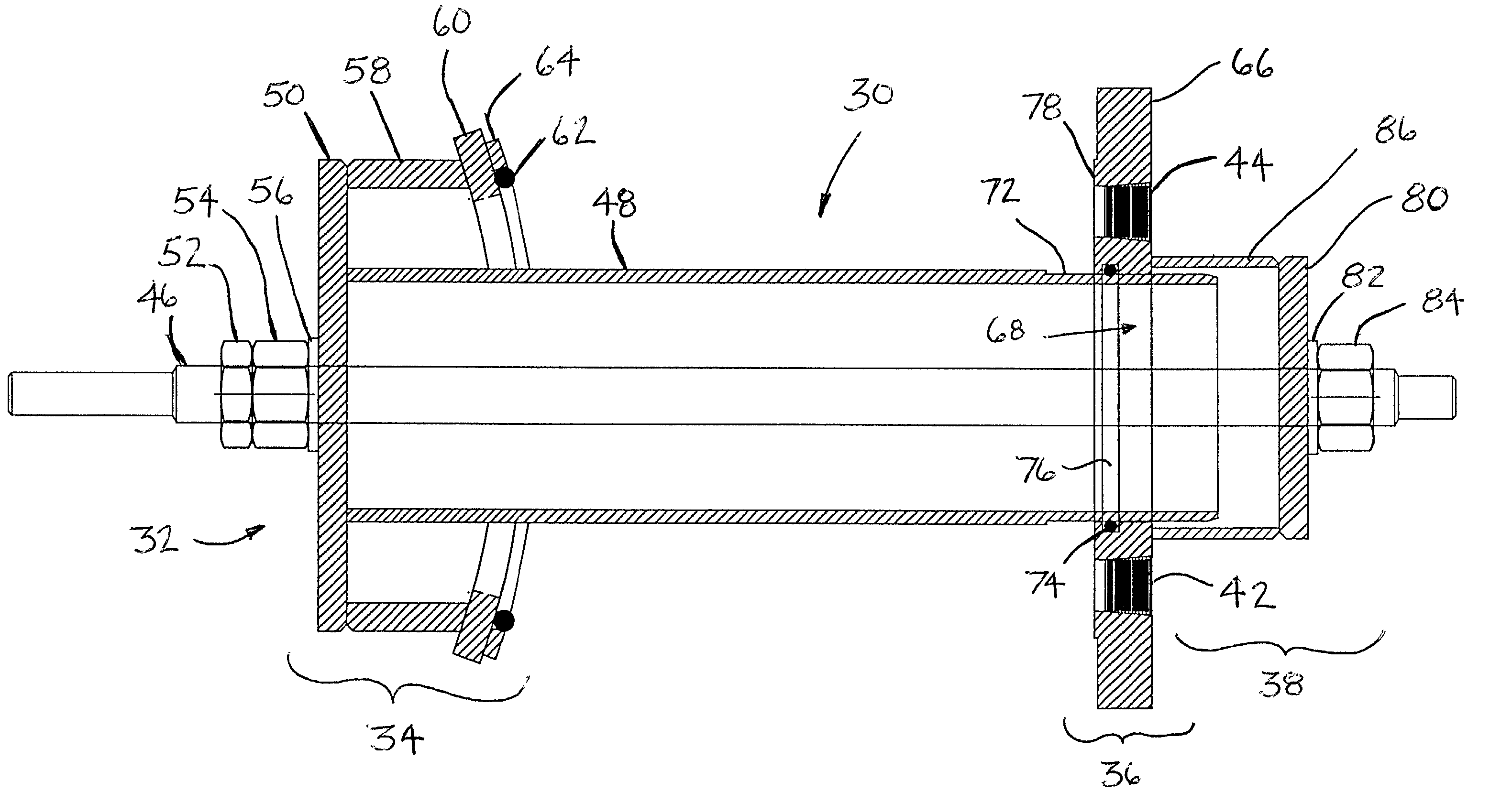
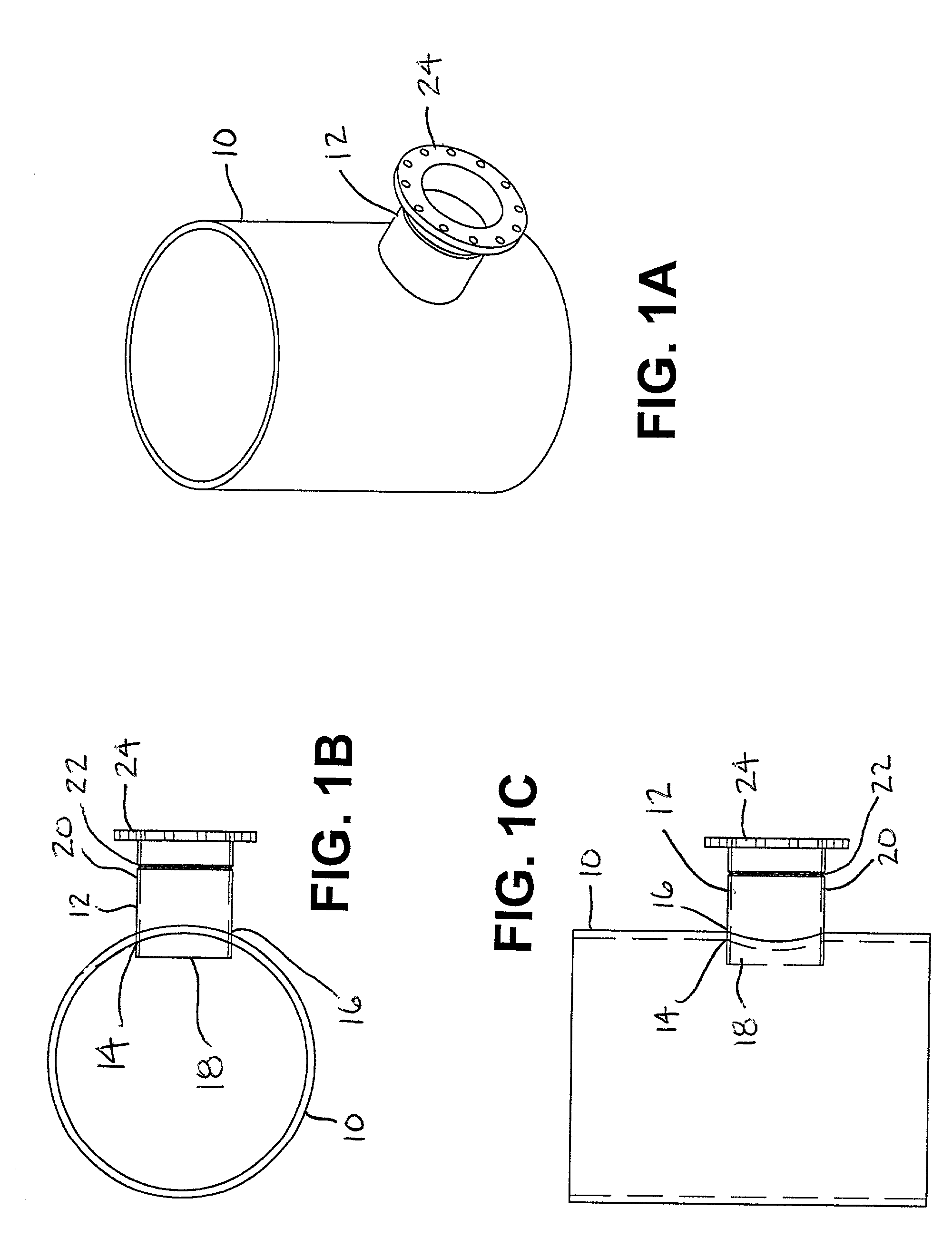
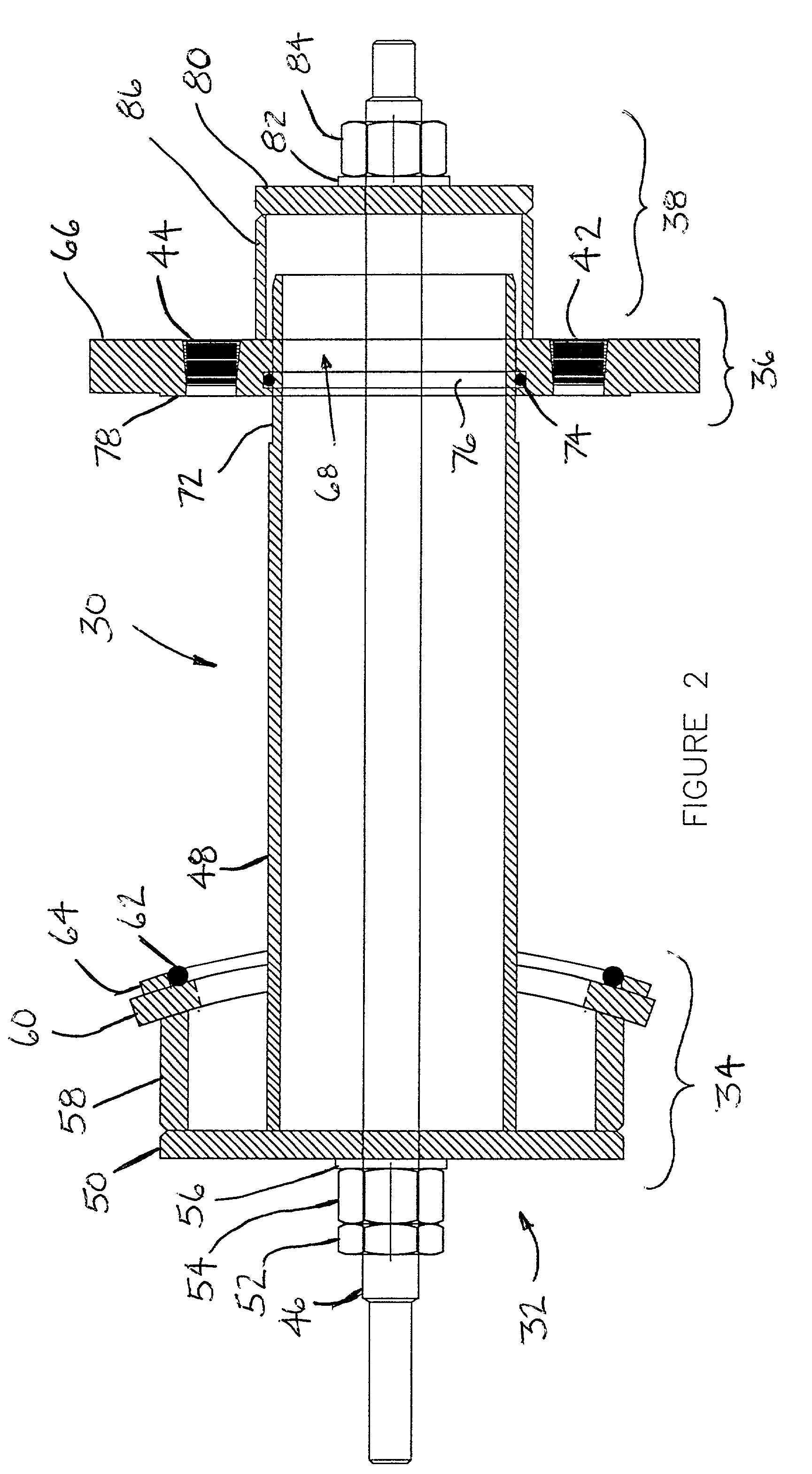
[0047] Another aspect of the present invention relates to a method of isolating and pressure testing a connection between a tank, vessel, or pipe and an externally extending nozzle or branch pipe. Test plugs 30 or 120 are utilized when the nozzle or branch pipe has a flanged end, and test plug 94 is utilized when the nozzle or branch pipe is without a flanged free end.

[0048] When the branch connection 12 has a flanged end 24, the annular plate 66 of the test plug 30 is connected to the flanged end 24 with a set of bolts. The annular gasket 78 ensures the formation of a fluid-tight seal between the annular plate 66 and the flanged end 24. Thereafter, the inner subassembly 32 of the test plug 30 is inserted through end 18 of the branch connection 12 within the tank, vessel, or pipe section 10. Thus, the sealing means 34 extends over end 18 of the branch connection and isolates it from the remainder of the tank, vessel or pipe section 10, and the spacing tube 48 extends through the bra...


PUM


Abstract

A test plug and method for isolating and testing a connection, such as a welded connection, which interconnects a wall of tank, vessel, or pipe to a branch pipe or nozzle. The test plug isolates the connection from the remainder of the tank, vessel or piping system and enables pressure / leak testing of the connection without requiring pressurization of the entire tank or vessel or a large section of the piping system. Further, the test plug can be utilized during welding operations to isolate harmful materials, vapors or fumes existing within tanks, vessels or piping systems from the weld location and to permit the flow of an inert gas to safely flush any potentially harmful vapors or the like away from the welding area.

Description

[0001] The present invention relates to a test plug and method for isolating and pressure testing a connection between a tank, vessel, or pipe and a nozzle or branch pipe extending externally therefrom.[0002] Site specifications, applicable design codes, and / or applicable testing codes typically require testing of new or modified piping, tank, and / or vessel systems including the testing of connections made between all piping components. The testing can be, for instance, a positive pressure test or a vacuum test and must verify the structural integrity of the system and determine if any leaks exist within the system, particularly at pipe connection locations. U.S. Pat. No. 5,797,431 issued to Adams, which is assigned to EST Group Inc., the assignee of present application, and U.S. Pat. No. 5,024,079 issued to Dufort disclose examples of known test plugs.[0003] The Adams patent discloses a test plug which is used to seal a non-flanged end of a pipe. To this end, the test plug is inser...

Claims


Application Information

Patent Timeline
Patent Type & Authority Applications(United States)
IPC IPC(8): G01M3/28
CPCG01M3/2884
Inventor BERNESKI, JAMES P. JR.BRANDENBERGER, HENRY
Owner EST GROUP
Why Eureka
Try Eureka