Eureka AIR delivers breakthrough ideas for toughest innovation challenges, trusted by R&D personnel around the world.

Bifunctional Catalyst for Decomposition and Oxidation of Nitrogen Monoxide, Composite Catalyst Including the Same for Apparatus to Decrease Exhaust Gas, and Method for Preparation Thereof

a nitrogen monoxide and bifunctional technology, applied in the direction of physical/chemical process catalysts, metal/metal-oxide/metal-hydroxide catalysts, separation processes, etc., can solve the problems of catalyst activity being too low to be used in a catalyst system, catalyst durability is insufficient, and maintenance costs increas

Inactive Publication Date: 2011-10-27
KOREA INST OF ENERGY RES
View PDF8 Cites 7 Cited by
  • Summary
  • Abstract
  • Description
  • Claims
  • Application Information

AI Technical Summary

Benefits of technology

[0024]Another object of the present invention is to provide a composite catalyst for an exhaust gas reducing device mounted on a diesel vehicle, which is applied to the device to improve efficiency of oxidizing un-combustible hydrogen carbide, carbon monoxide, nitrogen oxide, PM (particulate matter in exhaust gas), which are harmful to the human body, as well as the collection efficiency of carbon nanoparticles having a size of 30 nm or less.
[0030]According to the present invention, an average particle diameter of the support may be larger than that of the composite active metal. Since average particle diameters are different therebetween, if a composite catalyst of the present invention is applied to an exhaust gas reducing device mounted on a diesel vehicle, a contact area between the composite catalyst and exhaust gas may be increased.
[0031]As a result, the exhaust gas reducing device coated with the composite catalyst mounted on the diesel vehicle may improve oxidation efficiency of harmful materials such as PM (particulate matter in exhaust gas) and collection efficiency of carbon nanoparticles having a size of 30 nm or less.
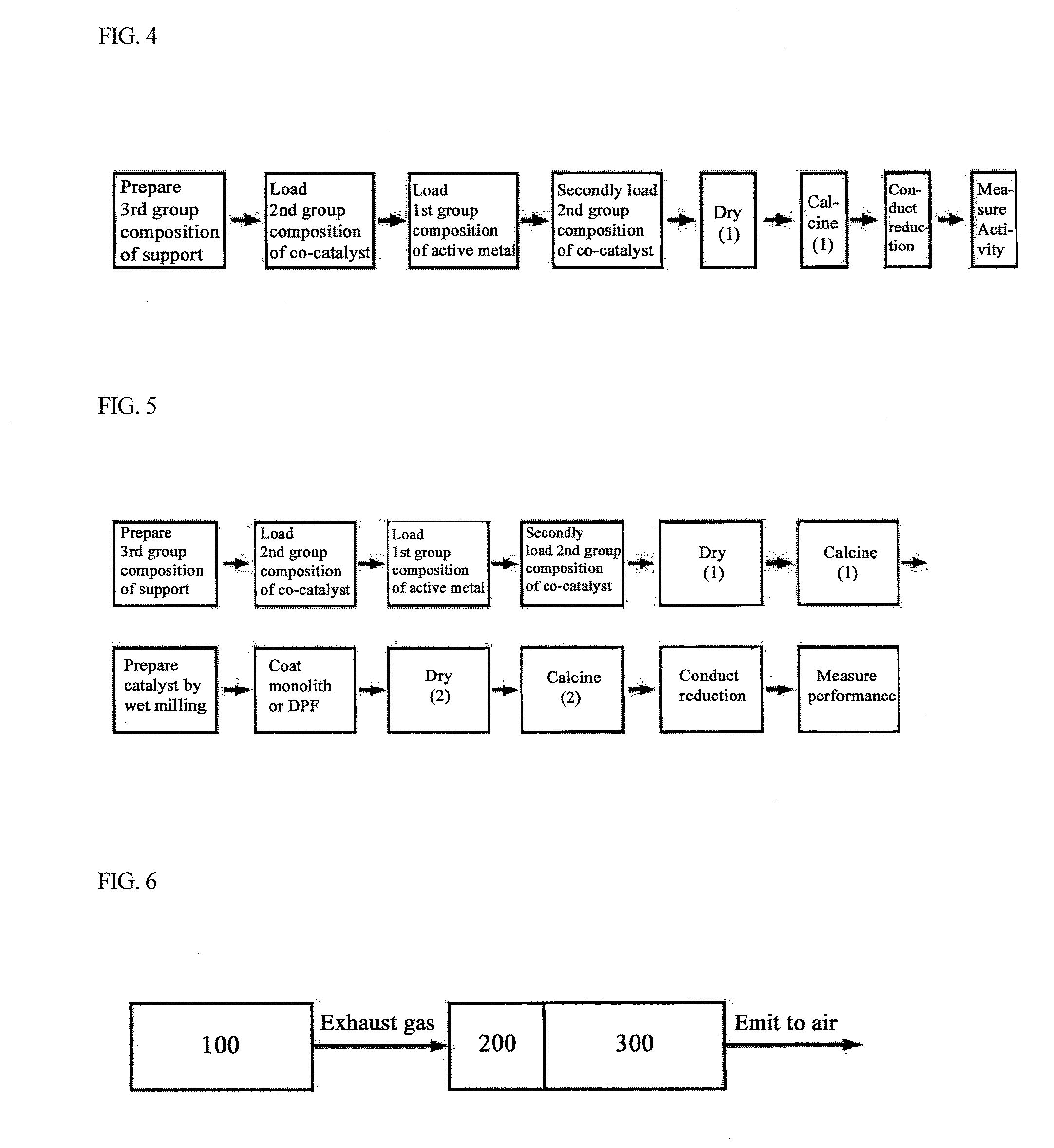
[0062]The construction shown in FIG. 5 is applicable to an engine which emits exhaust gases having a very high NOx / PM ratio of 20 or more. However, if the NOx / PM ratio is low, nitrogen oxide may be decomposed by the catalysts of the catalyst coated honeycomb 200. Further, NO2 selectivity is commonly 40% or less, thereby the above construction cannot provide a sufficient amount of oxidant (NO2) required for PM oxidation. Accordingly, a catalyst coated honeycomb may be fabricated by applying the inventive catalyst to an inner side of DPF 310, in particular, to a surface of honeycomb and used to improve utilization of NO (see Equations 1 and 2 above). According to the fabricated honeycomb, when the DPF is exposed to a high temperature, PM contacting with the catalyst may be directly oxidized (see Equation 4) and, at the same time, NO reduced into an original condition by Equation 3 is again subjected to reaction according to Equation 2, thus generating NO2. Therefore, the catalyst coated honeycomb according to the present invention may enhance NO use efficiency, in turn increasing an amount of PM to be removed.C(PM)+O2→CO2(or CO)  Equation 4
[0063]The exhaust gas purification system according to the present invention may have an alternative construction shown in FIG. 8. According to the construction shown in FIG. 8, decomposition rate of nitrogen oxide may be improved, compared to the construction shown in FIG. 7. About 10 to 30% of NO among a total volume of NOx contained in exhaust gas emitted from the engine 100 may be decomposed by the catalyst of the catalyst coated honeycomb 200 to generate N2. On the other hand, about 10 to 40% of NO may be oxidized into NO2. Since NO2 is reduced into NO while oxidizing PM in the DPF 310, an amount of NO2 remaining in the exhaust gas emitted from the DPF ranges from 65 to 85% relative to an initial concentration of NOx.
[0064]The foregoing passes through a rear catalyst coated honeycomb 210, thus further decreasing nitrogen oxide by 10 to 30%. Consequently, a total NO decomposition efficiency may become 20 to 50%, therefore, the above construction may be effective when it is applied to vehicles having high NOx / PM ratio.

Problems solved by technology

However, the foregoing entails disadvantages of high concentration of nitrogen oxides which refer to both of nitrogen monoxide (NO) and nitrogen dioxide (NO2) (hereinafter, referred to as ‘NOx’.
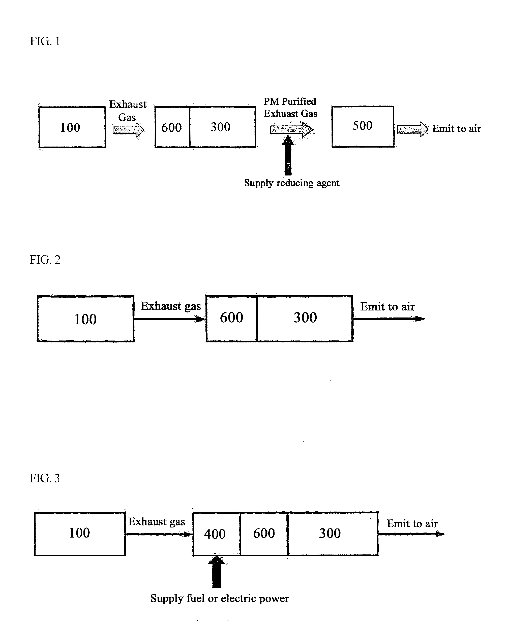
However, as shown in FIG. 1, a NO removing system using a reducing agent needs a device for supplying the reducing agent and alternative reduction catalyst (SCR) 500 for removing NOx, thus incurring increased cost of maintenance due to supply of the reducing agent as well as initial investment costs.
However, since the foregoing catalyst is activated at a high temperature of 500° C. or more, activity of the catalyst is too low to be employed in a catalyst system for removing exhaust gas having a distribution of considerably low temperatures and the catalyst has insufficient durability.
In addition, due to a great amount of oxygen, moisture, sulfur, etc., contained in vehicle exhaust gas, the activity of the catalyst is considerably decreased, in turn requiring some reinforcement.
In this case, as an amount of PMs accumulated in the filter is increased, problems such as engine overload may be caused.
The latter, that is, the forced regeneration system requires a great amount of energy to elevate a temperature of exhaust gas to a regeneration temperature of 500° C. or more, in other words, involves excessive consumption of fuel, and entails a problem of deterioration in fuel economy due to repeated regeneration or increased pressure caused by PMs.
However, for vehicles having the foregoing system, a coefficient of NO utilization in a conventional catalyst system is relatively low.
Meanwhile, vehicles having difficulty in applying the continuous regeneration type exhaust gas treatment system, e.g., a vehicle driven at a low speed in urban areas must have a forced regeneration type device for post-treatment of exhaust gas shown in FIG. 3.
Compared to the continuous regeneration type system for treatment of exhaust gas shown in FIG. 2, the foregoing system encounters a problem of increasing maintenance costs due to operation of the heater 400 to supply thermal energy.
In particular, if a regeneration cycle is short, maintenance costs for heating the exhaust gas are considerably increased.

Method used


Image

  • Bifunctional Catalyst for Decomposition and Oxidation of Nitrogen Monoxide, Composite Catalyst Including the Same for Apparatus to Decrease Exhaust Gas, and Method for Preparation Thereof
  • Bifunctional Catalyst for Decomposition and Oxidation of Nitrogen Monoxide, Composite Catalyst Including the Same for Apparatus to Decrease Exhaust Gas, and Method for Preparation Thereof
  • Bifunctional Catalyst for Decomposition and Oxidation of Nitrogen Monoxide, Composite Catalyst Including the Same for Apparatus to Decrease Exhaust Gas, and Method for Preparation Thereof

Examples


example 2

[0095]A catalyst was prepared by the same procedure described in Example 1, except that ZrO2 was used as a support of the catalyst (referred to as KOC-2).

[0096]For KOC-2 catalyst prepared as described above, after conducting reduction at 300° C. for 30 minutes using a reductant gas (10 vol %, H2 / N2) and before conducting NOx decomposition experiments, performance of the catalyst was evaluated. FIG. 9 illustrates NOx decomposition efficiency while FIG. 10 shows NO2 generation efficiency.

[0097]As a result of determining catalyst activity, it can be seen that NOx decomposition capability was greatly improved as compared to Pt[5] / γ—Al2O3, and NOx decomposition capability and NO2 generation selectivity were greatly improved as compared to commercially available catalysts.

example 3

[0098]Pt[2]-W[5] / TiO2 was prepared by loading, drying and calcining active metal and co-catalyst according to the same procedures described in Example 1. In order to improve NOx decomposition capability and durability, tungsten (W) among a second group of co-catalysts was additionally loaded in an amount of 1.0 wt. % relative to a total weight of the support. Then, drying, calcining and reduction were conducted to prepare a catalyst. Such prepared catalyst was indicated to as KOC-3.

[0099]For KOC-3 catalyst prepared as described above, after conducting reduction at 300° C. for 30 minutes using a reductant gas (10 vol %, H2 / N2) and before conducting NOx decomposition experiments, activity of the catalyst was evaluated. FIG. 9 illustrates NOx decomposition efficiency while FIG. 10 shows NO2 generation efficiency.

[0100]As a result of determining catalyst activity, it can be seen that NOx decomposition capability and NO2 generation selectivity were greatly improved as compared to Pt[5] / γ...

example 4

[0101]A slurry solution was prepared by wet milling the catalyst KOC-1 powder according to Example 1. Ceramic monolith (400 cpi) was immersed into the slurry solution to coat a surface of the monolith with catalyst component. Immersion and drying were repeated until an amount of the catalyst coating reached 60 g / L. After drying, the coated monolith was subjected to calcination at 550° C. for 4 hours in an air atmosphere, then, reduction at 300° C. for 1 hour in a 10 vol % hydrogen / nitrogen atmosphere, thereby forming a DOC.

[0102]By combining the completed DOC (diameter of 14 cm, length of 7.3 cm, 400 cpi) with ceramic DPF (diameter of 14 cm, length of 23 cm, 200 cpi), an integrated can was fabricated and used to manufacture a contaminant reducing device.

[0103]The exhaust gas reducing device was mounted on an automobile, for example, commercially available under the trade mane CARNIVAL (with TCI engine, KIA Motors, Korea) (see FIG. 11) and PM trapping amount depending upon time was m...


PUM

PropertyMeasurementUnit
particle diameteraaaaaaaaaa
temperaturesaaaaaaaaaa

Abstract

Disclosed are a bifunctional catalyst for simultaneously removing nitrogen oxide and particulate matters, capable of decomposing nitrogen monoxide and generating nitrogen dioxide through oxidation of nitrogen monoxide, a composite catalyst including the catalyst for simultaneously removing nitrogen oxide and particulate matters used for an apparatus to decrease exhaust gas of diesel vehicles, and a method for preparation thereof. The catalyst and the composite catalyst can be used in a device for reducing exhaust gas contaminants mounted on a diesel vehicle and an exhaust gas purification system comprising the device.

Description

RELATED APPLICATIONS[0001]This application claims priority to Korean Patent Application No. 10-2008-0126650, filed on Dec. 12, 2008, entitled, “Bi-functional catalyst for decomposing and oxidizing nitric oxide simultaneously and its preparation method therein”, which is incorporated herein by reference in its entirety; and also claims priority to Korean Patent Application No. 10-2009-0038462, filed on Apr. 30, 2009, entitled, “Mixtured catalyst for emission reduction device of diesel vehicles and preparing method for the same”, which is incorporated herein by reference in its entirety.TECHNICAL FIELD[0002]The present invention relates to a bifunctional catalyst for simultaneously removing nitrogen oxide and particulate matters, capable of decomposing nitrogen monoxide and generating nitrogen dioxide through oxidation of nitrogen monoxide, a composite catalyst including the catalyst for simultaneously removing nitrogen oxide and particulate matters used for an apparatus to decrease e...

Claims


Application Information

Patent Timeline
Patent Type & Authority Applications(United States)
IPC IPC(8): F01N3/035
CPCB01D53/9413B01D2255/1021B01D2255/20776B01D2255/502B01D2258/012B01J23/6527B01J23/89B01J29/7615B01J29/7815B01J35/023F01N3/0231B01J23/652B01J35/40
Inventor PARK, JONG-SOOHWANG, KYUNG-RANLEE, YOUNG-JAEJEONG, SOON-KWANKIM, DONG-KOOKCHOLEE, CHUN-BOOYOO, KYUNG-SUNCHOI, SEUNG-HOON
Owner KOREA INST OF ENERGY RES
Why Eureka
Eureka Blog
Learn More