

Method and apparatus for balancing a motor vehicle wheel
a technology for motor vehicles and wheels, applied in vehicle tyre testing, measurement devices, instruments, etc., can solve the problems of motor vehicle wheels sliding on the main shaft, wheel disk damage, clamping shaft bending risk, etc., to achieve high braking torque, reduce torque, and high torque
- Summary
- Abstract
- Description
- Claims
- Application Information
AI Technical Summary
Benefits of technology
Problems solved by technology
Method used
Image

Examples
Embodiment Construction
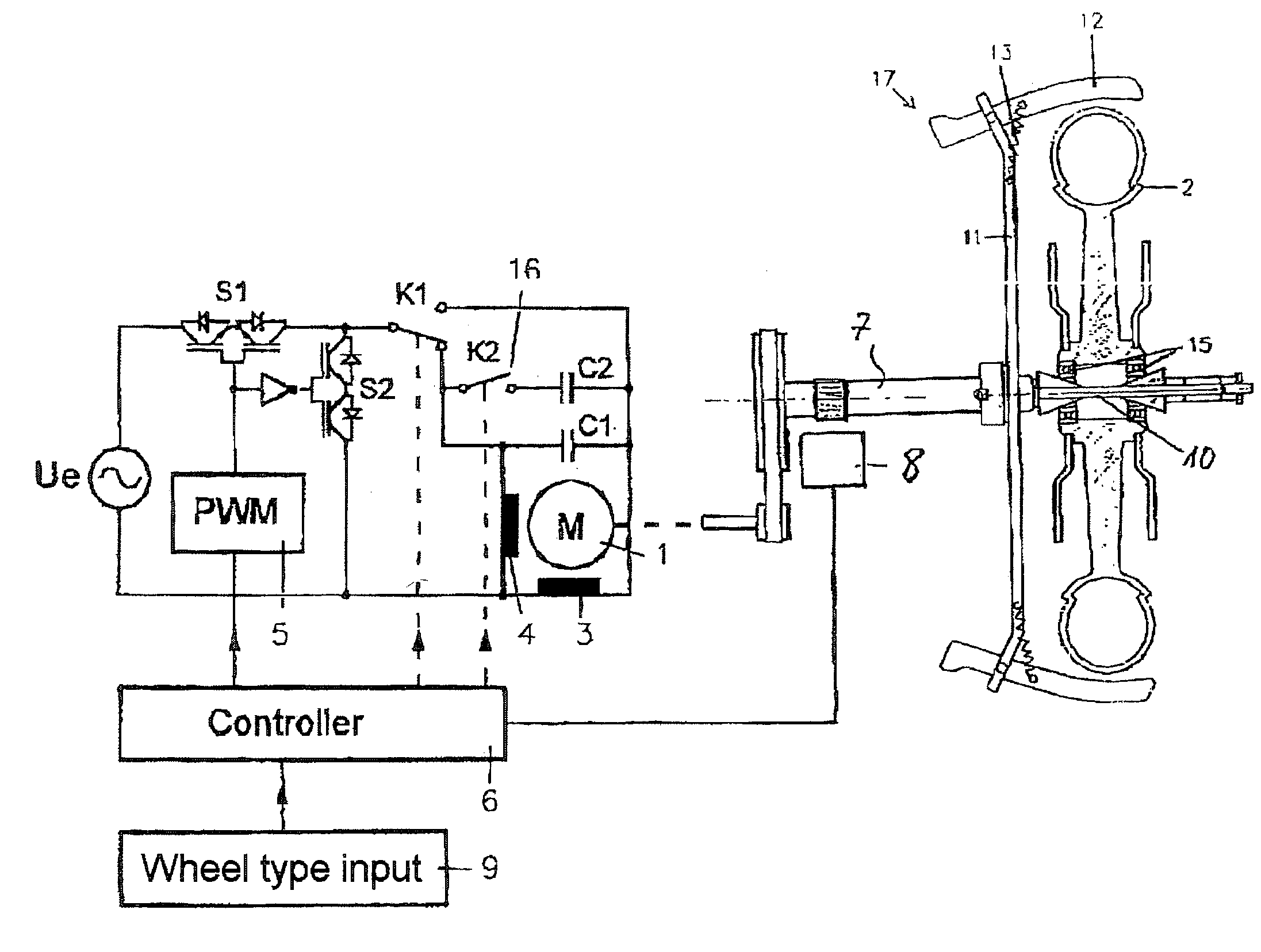
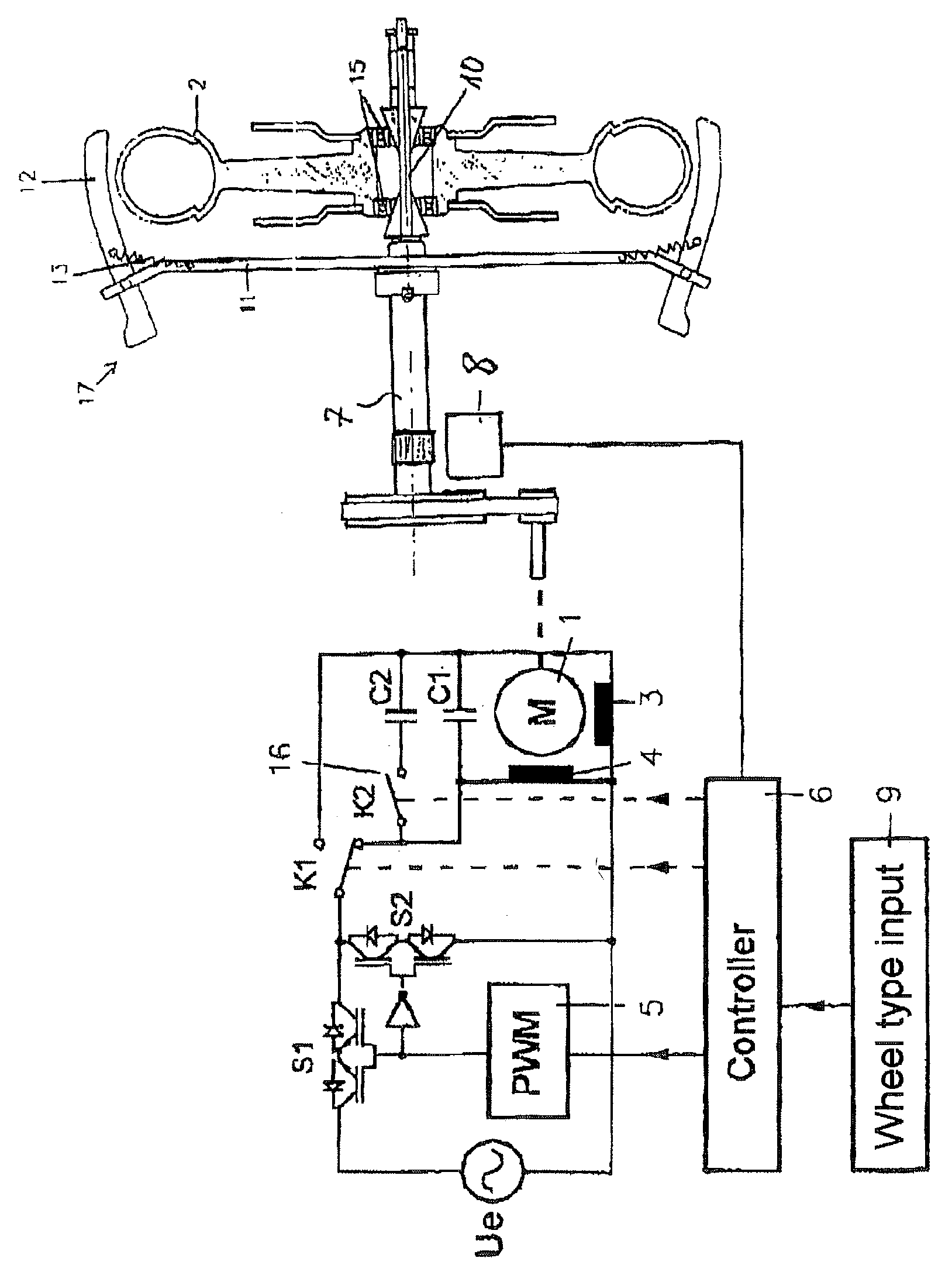
[0009] The invention will be explained in more detail using an exemplary embodiment and with reference to the figure.
[0010] The figure uses a block diagram to illustrate schematically a measurement arrangement and a drive arrangement for a wheel balancing machine.
[0011] The illustrated exemplary embodiment shows a main shaft 7 of a balancing machine which can be driven by an electric motor 1 via a transmission, for example belt drive. The electric motor is in the form of an AC motor, in particular a single-phase AC motor, as is known by way of example for a wheel balancing machine from DE 100 00 235 A1. A motor vehicle wheel 2 is clamped in a known manner onto the main shaft 7 of the balancing machine. The illustrated exemplary embodiment relates to a motor cycle wheel. In order to measure any unbalance, the main shaft 7 and the motor vehicle wheel 2 are driven by the electric motor 1 such that they accelerate to the measurement rotation speed. During the measurement run, forces whi...
PUM
 Abstract
Description
Claims
Application Information