Impact machine and a method of forming a body

Inactive Publication Date: 2003-09-11
MORPHIC TECH
View PDF4 Cites 11 Cited by
  • Summary
  • Abstract
  • Description
  • Claims
  • Application Information

AI Technical Summary

Problems solved by technology

The stress on all joints therefore become very large, as well as on sensitive components, e.g. electronic components for controlling those hydraulic valves which usually form parts of impact machines, which may cause a great risk of failure.
Large, unwieldy stands also give rise to problems in connection with service, change of tool unit or of tool insets in the tool unit, changing the height of the impact unit above the tool unit, etc.
Another problem with known impact machines of the said type is that they have a comparatively small production capacity.
This basically is due to the clumsiness of the machines, which makes it difficult to provide the machine with devices which would make a rational production possible.
Therefore, the consolidated body can be comparatively brittle and should be handled carefully, before it has been pushed out of the die and been heated to a sintering temperature in a subsequent operation, so tha

Method used


Image

  • Impact machine and a method of forming a body
  • Impact machine and a method of forming a body
  • Impact machine and a method of forming a body

Examples


Embodiment Construction

[0132] In a conceived case, the masses, the cross-section areas, and the stroke lengths were the following:

[0133] The pressure in the working chamber of the impact cylinder=300 bar.

[0134] The total mass m.sub.1 of the impact piston and the impact body (in the upper impact unit 2)=350 kg.

[0135] The stroke length s.sub.1 of the impact piston=100 mm.

[0136] The displaced volume in the return chamber of the impact cylinder=500 cm.sup.3.

[0137] The cross-section area A.sub.1 of the working chamber 245 of the converter 240=200 cm.sup.2.

[0138] The cross-section area A.sub.2 of the secondary chamber 242 of the converter 242=10 cm.sup.2.

[0139] The cross-section area A.sub.B of the four working chambers 209 of the lifting cylinders 205=50 cm.sup.2.

[0140] The pressure in the working chamber 245 of the converter 240=about 19 bar.

[0141] The total mass of the anvil assembly.congruent.7000 kg.

[0142] When the above conditions apply, the anvil assembly, i.e. the anvil 200 with the tool unit 32', will ...


PUM

PropertyMeasurementUnit
Lengthaaaaaaaaaa
Shapeaaaaaaaaaa

Abstract

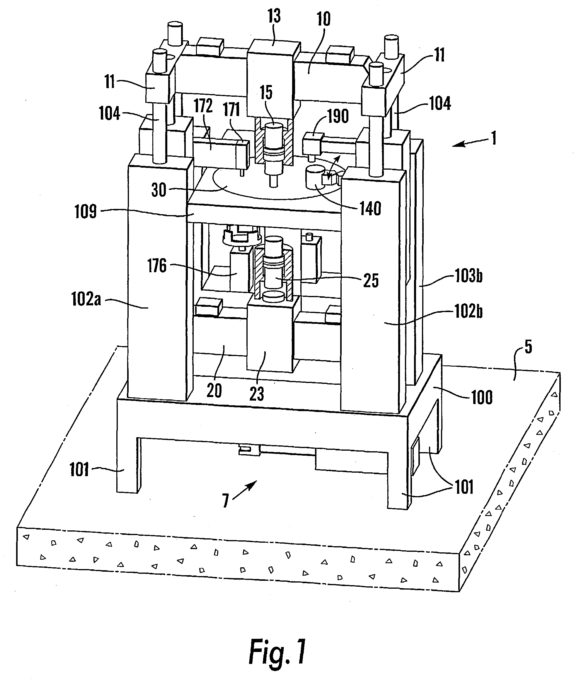
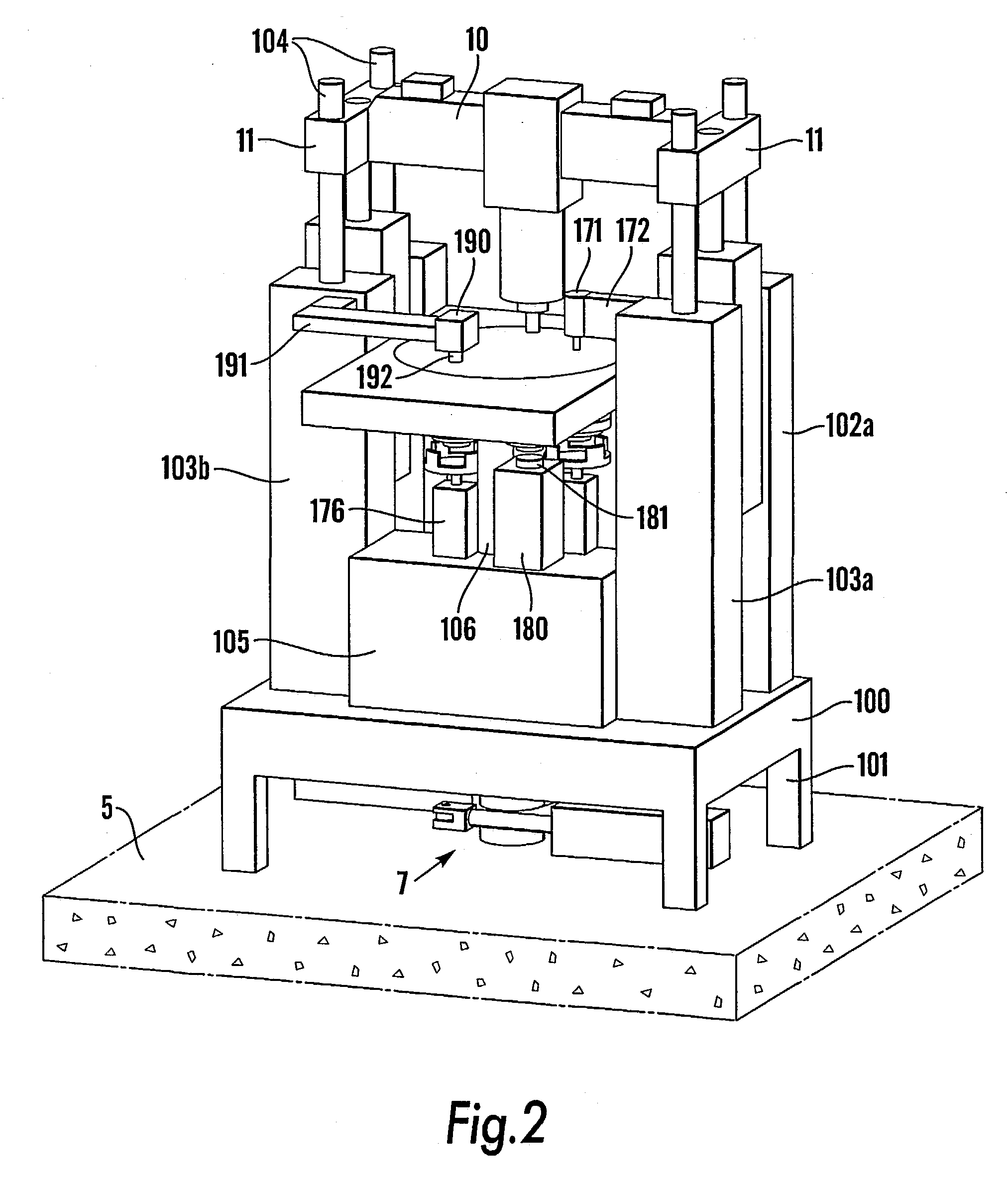
The invention concerns an impact machine for forming a body with desired shape of a formable working material through impact action in a forming operation, said impact machine comprising a machine stand (6), an upper unit which comprises either a lower impact unit (3), which comprises a counter-impact device, or a stationary anvil, and a central unit between the upper and the lower units. The central unit (4) comprises one or more carriers (30), each of which containing and carrying one or a plurality of identically equal tool units (32), each of which comprising a die (34) with a mould cavity (46) for the working material (90) intended to be formed, said carriers including at least one carrier which is stationary during the forming operation and which contains at least one such tool unit, and that motion devices (7) are provided for indexing the carrier or carriers in a horizontal plane for positioning the tool units in different function stations (I-V), comprising a forming station (II) and at least one more station.

Description

[0001] The invention concerns an impact machine for forming a body with desired shape of a formable working material through impact action in a forming operation, said impact machine comprising a machine stand, an upper unit which comprises an upper impact unit with an upper ram and an upper punch, a lower unit which comprises either a counter-impact device or a stationary anvil, and a central unit between the upper and the lower unit. The invention also concerns a method of forming a body of formable working material of such a machine.STATE OF THE ART[0002] Impact machines for working by the employment of high kinetic energy are machines for working in the first place metal, such as cutting, punching, and plastic forming of powder components, powder compaction, and similar operations, in which the speed of a ram, which may consist of a press piston, may be essentially higher than in conventional presses. Also polymeric and ceramic working materials can be conceived, as well as vari...

Claims


Application Information

Patent Timeline
IPC IPC(8): B21J9/02B22F3/03B22F3/17B30B11/02B30B11/08
CPCB21J9/02B22F3/03B30B11/08B29C2043/3618B30B11/027B22F3/17B30B15/0023B30B11/10B21J7/06B21J7/28
Inventor OLSSON, HAKAN
Owner MORPHIC TECH
Why Eureka
Try Eureka