
Energy management system, energy management apparatus, and energy management method

a technology of energy management and energy management equipment, applied in the direction of electrical storage system, greenhouse gas reduction, instruments, etc., can solve the problems of how the load capable of consuming photovoltaic power generation amount can not be reduced by consumers, and achieve the effect of reducing the impact of the power system, increasing the amount of photovoltaic power generation amount, and generating and consuming power

Active Publication Date: 2011-09-29
HITACHI LTD
View PDF12 Cites 59 Cited by
  • Summary
  • Abstract
  • Description
  • Claims
  • Application Information

AI Technical Summary

Benefits of technology

[0009]To solve the above-described problem, it is an object of the present invention to provide a unit which can attain optimal operation of energy storage facilities for improving a total energy efficiency, avoiding the voltage increase suppression function of the photovoltaic power generation facilities, and maximizing a consumable amount in the consumption using the energy storage facilities of the photovoltaic power generation amount.
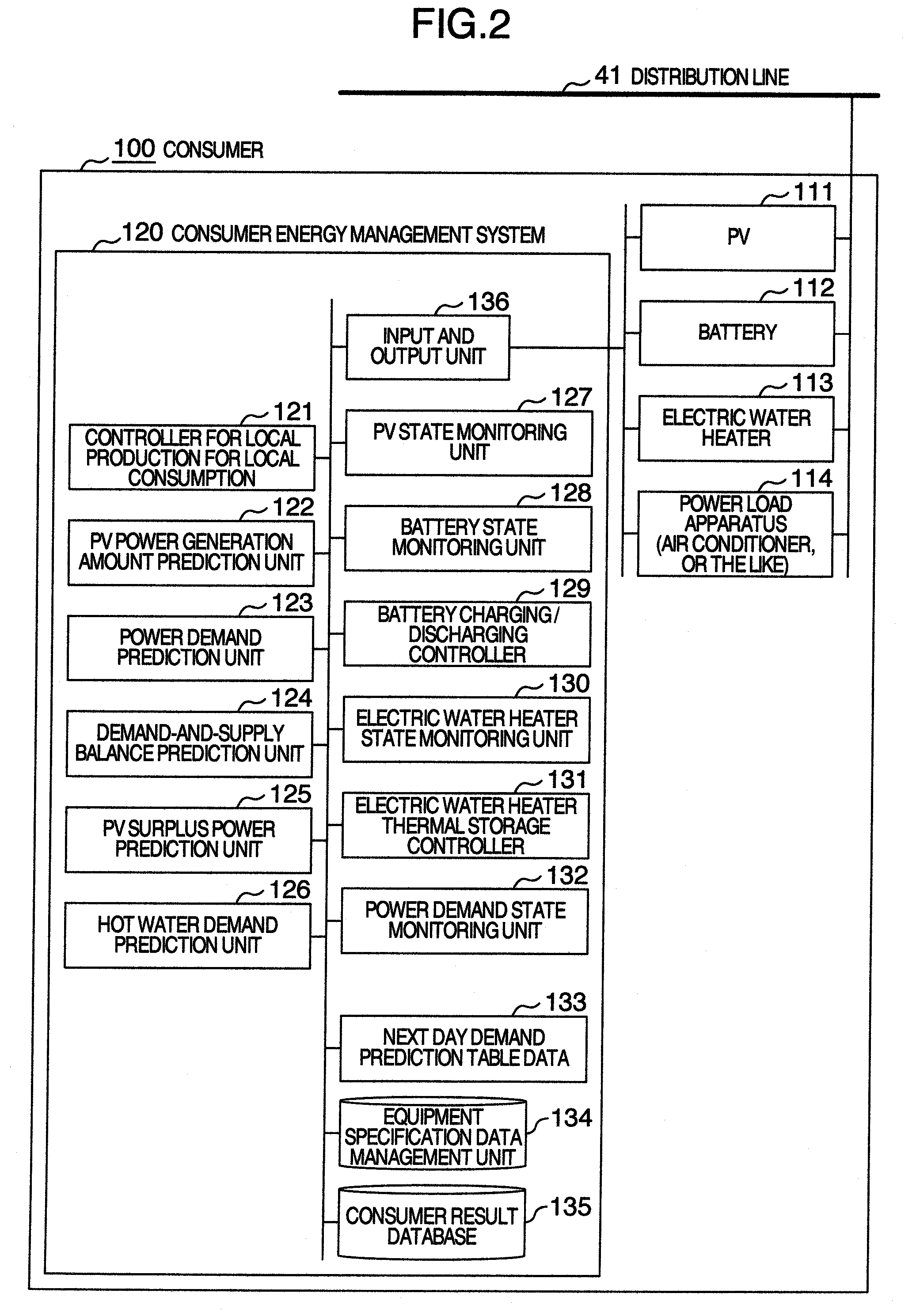
[0010]In view of the foregoing, it is an object of the present invention to provide an energy management system including an energy storage controller for performing control to store power generated by photovoltaic power generation facilities in energy storage facilities. According to one aspect of the present invention, this energy management system includes: a battery and an electric water heater as the energy storage facilities; a control unit to control thermal storage of the electric water heater and charging of the battery as the energy storage controller; and an equipment data management unit to manage data on charging / discharging loss of the battery and data on heat radiation loss of the electric water heater, wherein the equipment data management unit causes the control unit to perform control to compare the charging / discharging loss and the heat radiation loss, give priority based on the comparison to the energy storage facility more reducing loss and store energy therein.
[0013]According to the present invention, in cooperation and expansion to a power system of the photovoltaic power generation facilities, the energy management system can reduce an impact on the power system, increase the photovoltaic power generation amount on the consumer end, and generate and consume power with high efficiency and low carbon emissions.

Problems solved by technology

There arises the problem on the optimal operating method in which a charging operation of the battery and a thermal storage operation of the electric water heater are combined during the consumption of the photovoltaic power generation amount.
Further, there arises the possibility that when the power generation amount of the photovoltaic power generation facilities is larger than a capacity of the electric water heater or battery on the consumer end, the consumer cannot help suppressing the power generation amount of the photovoltaic power generation facilities.
There arises the problem as to how the amount of load capable of consuming the photovoltaic power generation amount.

Method used


Image

  • Energy management system, energy management apparatus, and energy management method
  • Energy management system, energy management apparatus, and energy management method
  • Energy management system, energy management apparatus, and energy management method

Examples


first embodiment

1. First Embodiment

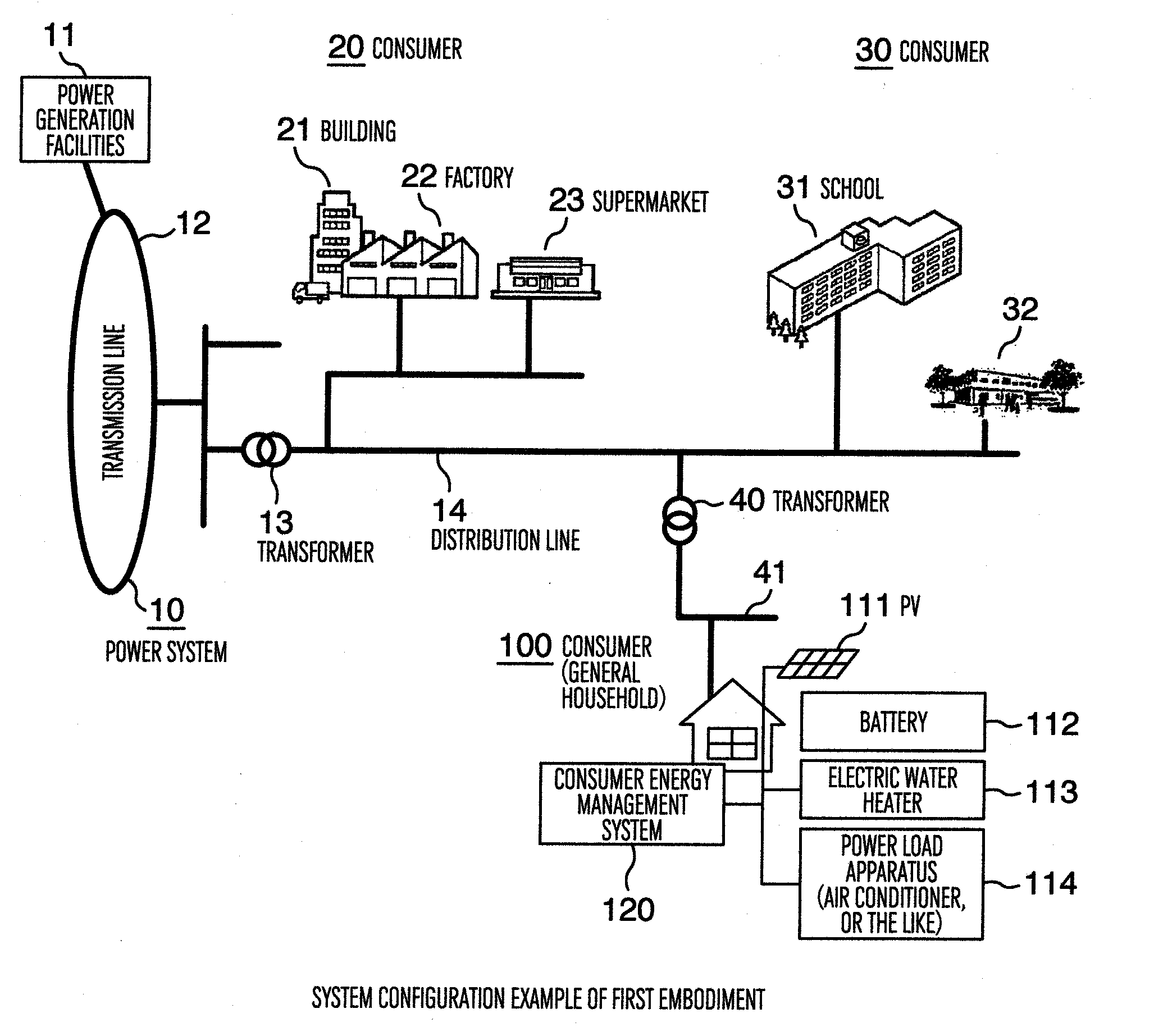
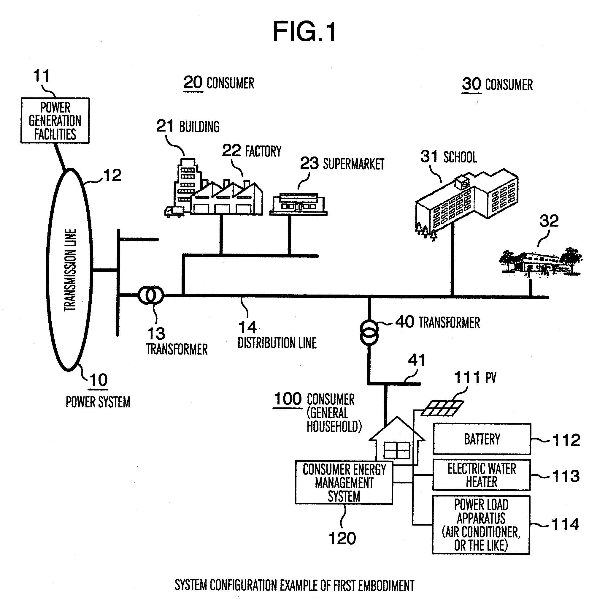
[0035]An energy management system according to a first embodiment of the present invention will be described with reference to FIGS. 1 to 8.

[0036]FIG. 1 illustrates the entire system configuration example according to the present embodiment.

[0037]In the present embodiment, the energy management system is configured by a power system 10 operated by an electric power company, consumers 20, 30, and 100 connected to the power system 10, and a consumer energy management apparatus 120 provided on the consumer 100.

[0038]The power system 10 supplies power acquired by power generation facilities 11 to a transformer 13 via a transmission line 12, and supplies power transformed by the transformer 13 via a distribution line 14 to buildings 21, factories 22, and supermarkets 23 as large-sized consumers 20. Further, the power system 10 supplies power also to schools 31, and community centers 32 as relatively large-sized consumers 30 in a residential district. Further, the power...

second embodiment

2. Second Embodiment

[0138]Next, the energy management system according to a second embodiment of the present invention will be described with reference to FIGS. 9 and 10. In FIGS. 9 and 10, the same circuit elements as those of FIGS. 1 to 8 in the first embodiment are indicated by the same reference numerals as those of FIGS. 1 to 8 in the first embodiment.

[0139]In an example according to the second example, an operating system for system cooperation type local production for local consumption is illustrated such that the consumer energy management apparatus operates in cooperation with a system operating system of a power system.

[0140]FIG. 9 illustrates the entire system configuration example according to the present embodiment. To the configuration illustrated in FIG. 1, a system operating system 51 and a consumer cooperation server 52 are added. The consumer energy management apparatus is changed into a system cooperation type consumer energy management apparatus 220. The consume...

third embodiment

3. Third Embodiment

[0170]Next, the energy management system according to a third embodiment of the present invention will be described with reference to FIGS. 11 to 14. In FIGS. 11 to 14, the same circuit elements as those of FIGS. 1 to 10 in the first and second embodiments are indicated by the same reference numerals as those of FIGS. 1 to 10 in the first and second embodiments.

[0171]In an example according to the third example, an operating system for community local production for local consumption is illustrated such that the consumer energy management apparatus operates cooperatively among a plurality of consumers.

[0172]FIG. 11 illustrates the entire system configuration example according to the present embodiment. To the configuration of FIG. 1, a community energy management apparatus 390 is added, and the consumer energy management apparatus is changed into a community-compatible consumer energy management apparatus 350. The community energy management apparatus 390 is an en...


PUM


Abstract

An energy management system includes an equipment data management unit which manages charging / discharging loss of a battery and heat radiation loss of an electric water heater, and causes a control unit to perform control to give priority based on the comparison to the energy storage facility more reducing loss and store energy. The energy management system includes a system operation calculation unit which predicts voltage distribution of the next day of a distribution system or demand-and-supply balance amount of the entire system by state monitoring data of a power system, calculates a demand amount increasing target value necessary for avoiding a photovoltaic power generation amount suppression on a consumer end by the voltage distribution of the next day of the distribution system or the demand-and-supply balance amount, and controls the energy storage facilities so as to satisfy the demand amount increasing target value on the consumer end.

Description

BACKGROUND OF THE INVENTION[0001]The present invention relates to an energy management system applied at the time of operating energy equipment such as photovoltaic power generation facilities, a battery, and an electric water heater on a consumer end, and an energy management apparatus applied to the system and which is installed on a consumer or in the vicinity of the consumer.[0002]Photovoltaic power generation facilities are assumed to be introduced and expanded in preparation for reduction in a load to global environment. However, the following is feared in cooperation and expansion to a power system of the photovoltaic power generation facilities. That is, due to a reverse power flow of photovoltaic generated power in a distribution system, a voltage rises up and a voltage control is influenced, or supply power of the entire system increases and a demand-and-supply balance control is influenced.[0003]As one method of measures, a time zone of a thermal storage operation in an e...

Claims


Application Information

Patent Timeline
IPC IPC(8): G06F1/28
CPCH02J3/32H02J7/35Y02E70/30Y02E10/566H02J15/00Y02P90/50Y02E10/56
Inventor TOMITA, YASUSHIWATANABE, MASAHIROEBARA, TAKAFUMIOTAKE, YUICHIKOBAYASHI, AKIRAKAWAMURA, HIDEYUKI
Owner HITACHI LTD
Learn More