
Helical antenna apparatus provided with two helical antenna elements, and radio communication apparatus provided with same helical antenna apparatus

Inactive Publication Date: 2003-09-18
PANASONIC CORP
View PDF2 Cites 27 Cited by
  • Summary
  • Abstract
  • Description
  • Claims
  • Application Information

AI Technical Summary

Benefits of technology

[0024] In the above-mentioned radio communication apparatus, the helical antenna apparatus further includes a detector and an adaptive controller. The detector is connected between (a) either one of the balanced feeder line and the feeding port of the balanced to unbalanced transformer, and (b) a radio transmitter, and the detector detects at least one detection value of a reflection signal reflected from the first and second helical antenna elements when the first and second helical antenna elements are fed with a transmission signal from the radio transmitter, a reflection coefficient and a voltage standing wave ratio. The adaptive controller adaptively controls respective capacitance values of the first, second and third variable capacitance elements, so that either one of the detected detection value and a predetermined estimation function including the reflection signal becomes substantially minimized.
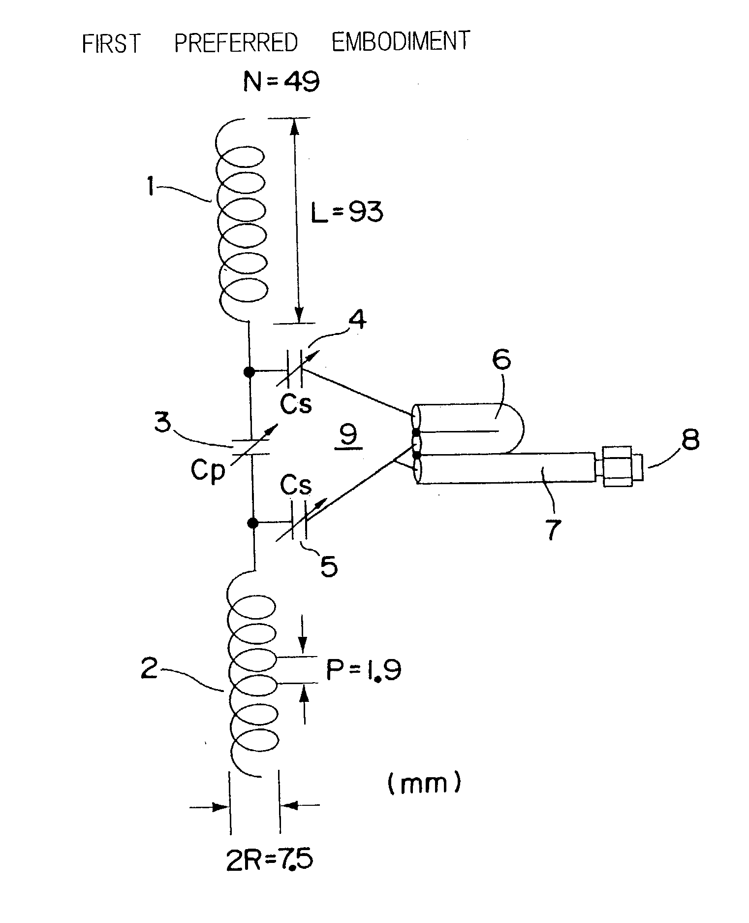
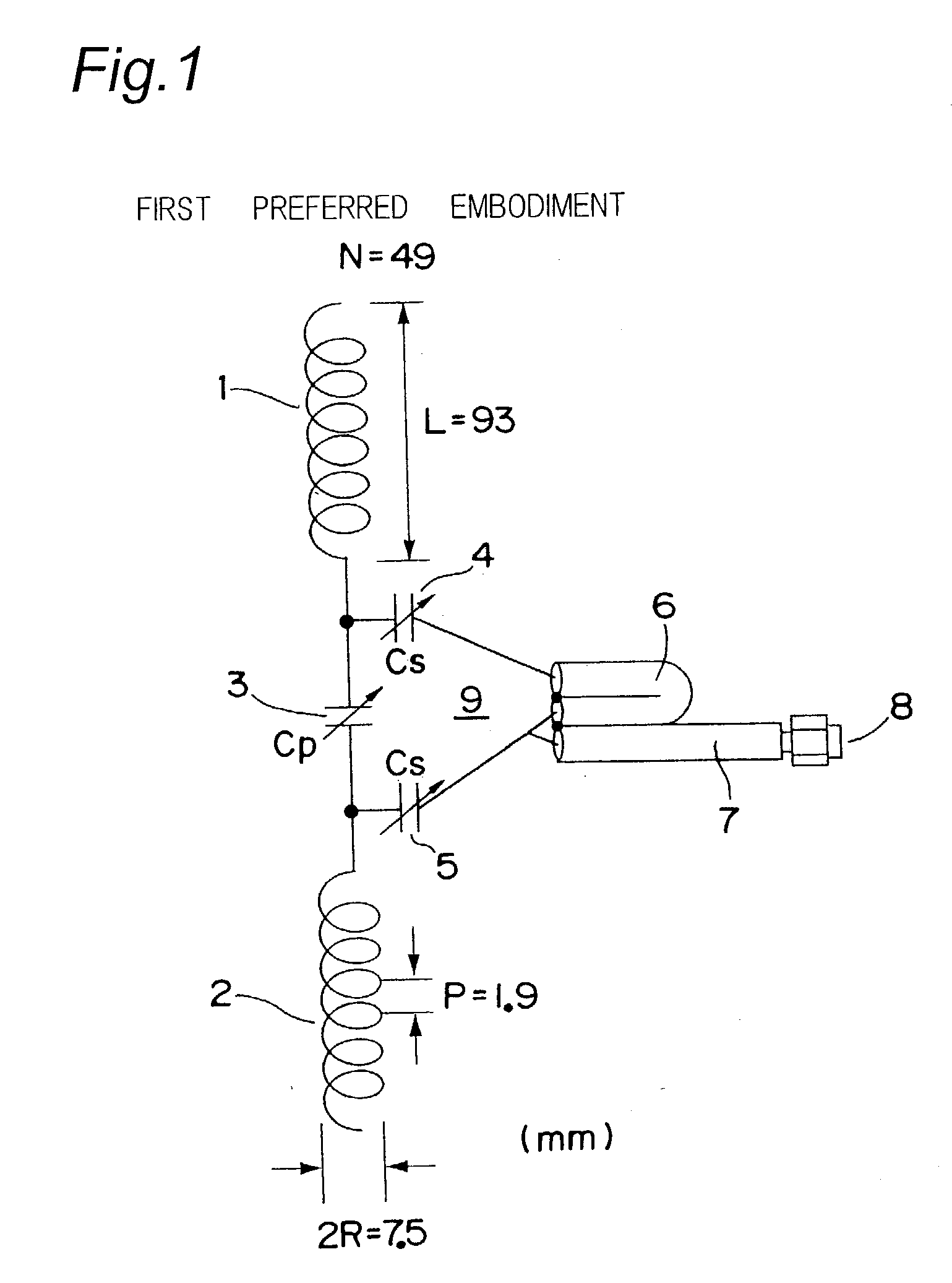
[0023] According to a further aspect of the present invention, there is provided a radio communication apparatus, which includes a helical antenna apparatus, a radio transmitter, a radio receiver. The helical antenna apparatus is connected to either one of a balanced feeder line and a balanced port of a balanced to unbalanced transformer of a feeder circuit. The radio transmitter is connected to the helical antenna apparatus, and the radio receiver connected to the helical antenna apparatus. The helical antenna apparatus includes first and second antenna elements and first to third variable capacitance elements. The first variable capacitance element is connected between the first helical antenna element and the second helical antenna element. The second variable capacitance element is connected between (a) either one of the balanced feeder line and a first terminal of the balanced port of the balanced to unbalanced transformer, and (b) the first helical antenna element. The third variable capacitance element is connected between (a) either one of the balanced feeder line and a second terminal of the balanced port of the balanced to unbalanced transformer, and (b) the second helical antenna element.

Problems solved by technology

Therefore, according to the impedance characteristic shown in FIG. 24, there arise such a problem that the actual gain of the helical antenna apparatus 102 is significantly reduced due to an impedance mismatching loss when the antenna apparatus is used at a frequency other than the frequency at which matching is achieved.
As described above, the first problem of the helical antenna for business radio use is that that the impedance characteristic has a narrow range.
As is comprehensible from the above-mentioned analytical results, the other problem of the helical antenna apparatus 102 of FIG. 22 is an increase in power loss due to impedance mismatching in a situation in which a human body is located so as to be close to the apparatus.
The first problem is the narrow range of the impedance characteristic, and the second problem is the increase in power loss due to impedance mismatching when a human body is located so as to be close to the apparatus.
However, in the helical antenna apparatus 102 of the prior art example shown in FIG. 23, the impedance matching has been achieved only at the specified frequency predetermined in free space, and this has therefore led to such a problem that the impedance frequency characteristic has had a narrow range.
Furthermore, there has been such a problem that, in the situation in which the helical antenna apparatus 102 has been located so as to be close to a human body, the mismatching situation has been promoted by the electromagnetic interaction between the helical antenna apparatus 102 and the human body even at the frequency at which the impedance matching is achieved in free space and the actual gain of the antenna has been significantly reduced.

Method used


Image

  • Helical antenna apparatus provided with two helical antenna elements, and radio communication apparatus provided with same helical antenna apparatus
  • Helical antenna apparatus provided with two helical antenna elements, and radio communication apparatus provided with same helical antenna apparatus
  • Helical antenna apparatus provided with two helical antenna elements, and radio communication apparatus provided with same helical antenna apparatus

Examples


Embodiment Construction

[0161] In the above-mentioned preferred embodiments, the variable capacitance elements 3, 4 and 5 are constituted by the switchover among the plurality of capacitors or the variable capacitance diodes. However, the present invention is not limited to this, and it is acceptable to employ a piezoelectric capacitor in which a dielectric material is interposed between the electrodes of a piezoelectric element. With this arrangement, the withstand voltage can be increased.

[0162] Advantageous Effects of the Preferred Embodiments

[0163] As described in detail above, according to the helical antenna apparatus of the preferred embodiment according to the present invention, there is provided a helical antenna apparatus connected to either one of a balanced feeder line and a balanced port of a balanced to unbalanced transformer of a feeder circuit. The helical antenna apparatus includes a first helical antenna element, a second helical antenna element, and first to third variable capacitance el...


PUM


Abstract

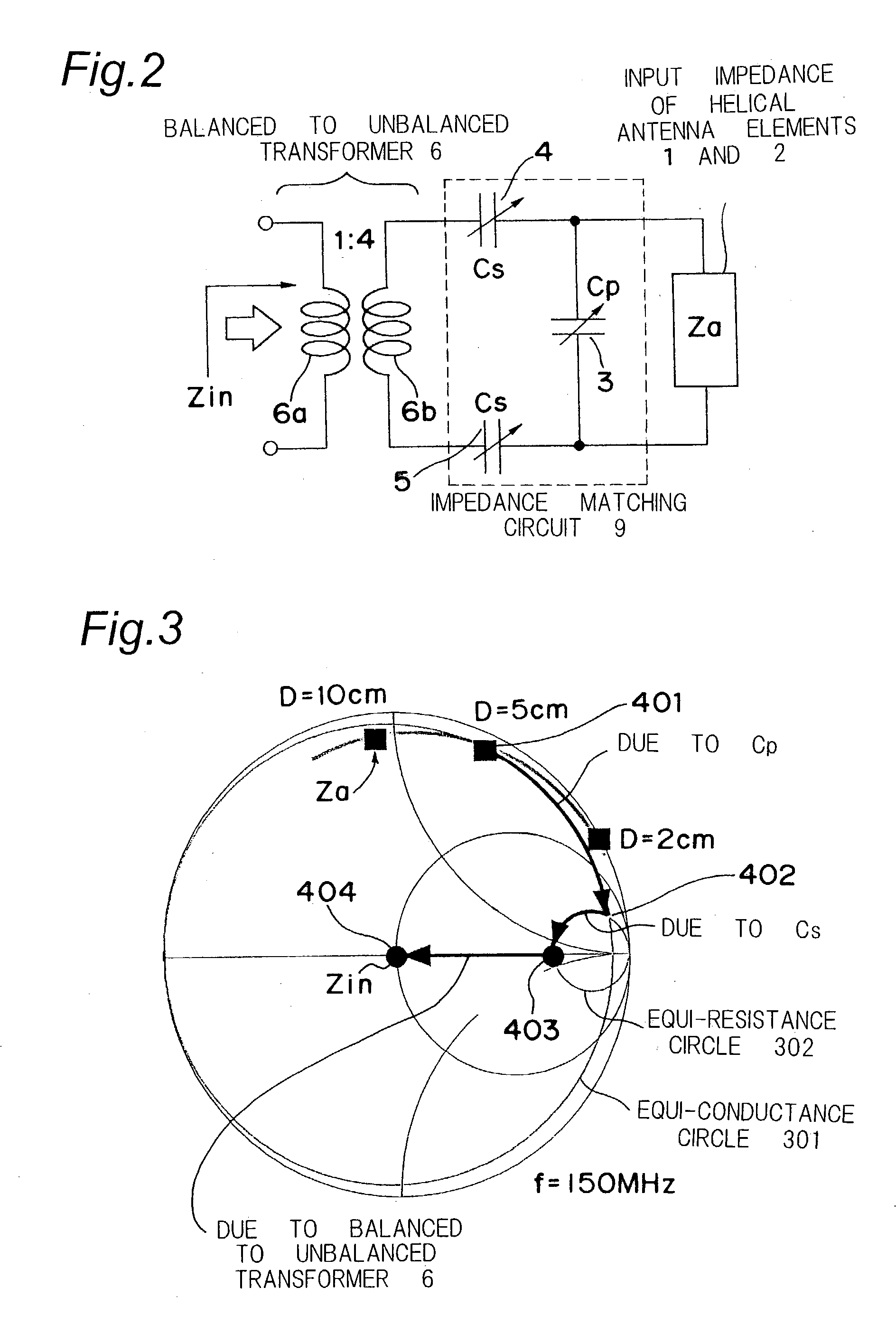
In a helical antenna apparatus, a first variable capacitance element is connected between a first helical antenna element and a second helical antenna element, and a second variable capacitance element is connected between a first terminal of a balanced port of a balanced to unbalanced transformer and the first helical antenna element. A third variable capacitance element is connected between a second terminal of the balanced port of the balanced to unbalanced transformer and the second helical antenna element. A detector measures a detection voltage Vd corresponding to a reflected power of a reflected signal reflected from the first and second helical antenna elements when the first and second helical antenna elements are fed with a transmission signal from a radio transmitter, and an adaptive controller adaptively controls respective capacitance values of the first to third variable capacitance elements.

Description

[0001] 1. Field of the Invention[0002] The present invention relates to a helical antenna apparatus provided with two helical antenna elements, and to a radio communication apparatus provided with the same helical antenna apparatus. In particular, the present invention relates to a helical antenna apparatus for use in a mobile radio system, such as, mainly in a portable telephone, a radio transceiver for business use or the like, and a radio communication apparatus provided with the same antenna apparatus.[0003] 2. Description of the Prior Art[0004] FIG. 22 is a perspective view showing one example of a situation in which a prior art portable radio transceiver 101 for business use is used. The VHF band of 150 MHz to 450 MHz is assigned as a radio frequency to the portable radio transceiver 101 for business use. Therefore, a normal-mode helical antenna apparatus 102 attached to the portable radio transceiver 101 is often employed as an antenna as shown in FIG. 22.[0005] FIG. 23 is a ...

Claims


Application Information

Patent Timeline
IPC IPC(8): H01Q1/24H01Q1/36H01Q11/08
CPCH01Q1/242H01Q11/08H01Q1/362
Inventor OGAWA, KOICHIIWAI, HIROSHIKOYANAGI, YOSHIO
Owner PANASONIC CORP
Learn More