Dual spin valve sensor with a longitudinal bias stack

a sensor and longitudinal bias technology, applied in special recording techniques, instruments, nanoinformatics, etc., can solve the problems of sensor stability still a major concern, magnetic stabilization of the sense layer can be difficult, and the gmr coefficient may not be high enough to ensure adequate signal

Inactive Publication Date: 2003-10-02
HITACHI GLOBAL STORAGE TECH NETHERLANDS BV
View PDF20 Cites 89 Cited by
  • Summary
  • Abstract
  • Description
  • Claims
  • Application Information

AI Technical Summary

Problems solved by technology

Two challenging issues are encountered when the CPP sensor is used for ever increasing magnetic recording densities.
First, the GMR coefficient may not be high enough to ensure adequate signal amplitude as the sensor width is decreased and second, magnetic stabilization of the sense layer can be difficult due to the use of insulating layers to avoid current shorting around the active region of the sensor.
However, sensor stability still remains a major concern.

Method used


Image

  • Dual spin valve sensor with a longitudinal bias stack
  • Dual spin valve sensor with a longitudinal bias stack
  • Dual spin valve sensor with a longitudinal bias stack

Examples


second example

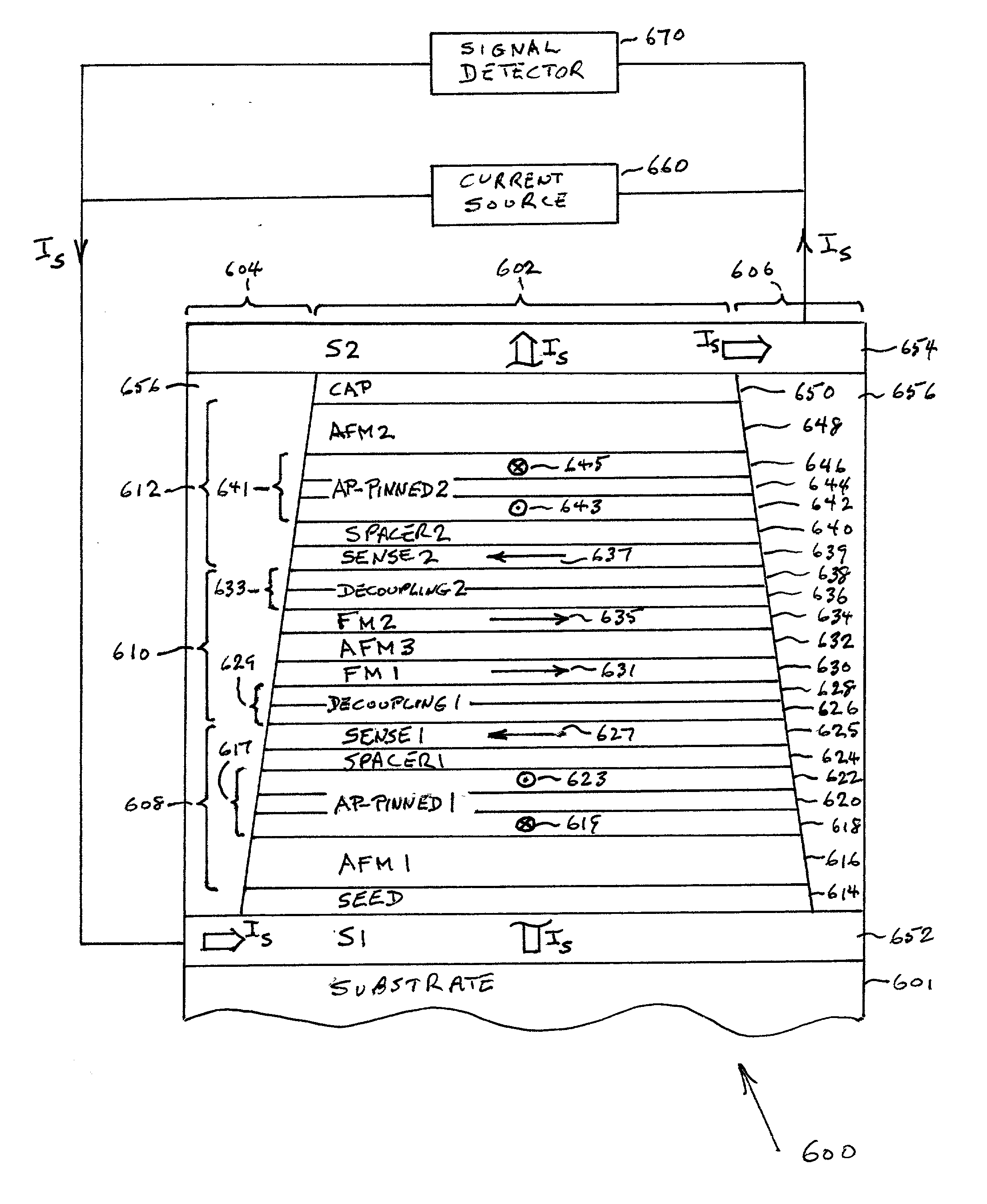
[0056] FIG. 7 shows an air bearing surface (ABS) view, not to scale, of a CPP dual spin valve (SV) sensor 700 according to another embodiment of the present invention. The dual SV sensor 700 is the same as the dual SV sensor 600 shown in FIG. 6 except that in order to achieve a read gap thickness of 50 nm the AFM1 and AFM2 layers 616 and 648 have been eliminated and the AFM3 layer 632 of the longitudinal bias stack 610 has been replaced by an AFM3 layer 716 of Pt--Mn having a thickness of 160 .ANG.. The dual SV sensor 700 comprises a first SV stack 708, a second SV stack 712 and a longitudinal bias stack 710 disposed between the first and second SV stacks 708 and 712. In this embodiment the first SV stack 708 is the same as SV stack 608 without the AFM1 layer 616 and the second SV stack 712 is the same as SV stack 612 without the AFM2 layer 648. The longitudinal bias stack 710 is the same as bias stack 610 with the AFM3 layer of Ir--Mn replaced with an AFM3 layer 716 of Pt--Mn havin...

third example

[0061] FIG. 8 shows an air bearing surface (ABS) view, not to scale, of a CPP hybrid spin valve (SV) / magnetic tunnel junction (MTJ) sensor 800 according to a another embodiment of the present invention. The hybrid SV / MTJ sensor 800 is the same as the dual SV sensor 600 shown in FIG. 6 except that one of the two SV stacks 608 and 612 is replaced with a magnetic tunnel junction (MTJ) stack. In the embodiment shown in FIG. 8, the second SV stack 612 has been replaced with an MTJ stack 812. However, alternatively, the first SV stack 608 may be replaced with an MTJ stack to form an alternative hybrid MTJ / SV sensor.

[0062] The SV / MTJ sensor 800 comprises an SV stack 608, an MTJ stack 812 and a longitudinal bias stack 610 disposed between the SV stack 608 and and the MTJ stack 812. In this embodiment the SV stack 608 and the longitudinal bias stack 610 are identical to the first SV and longitudinal bias stacks of the preferred embodiment shown in FIG. 6. The MTJ stack 812 deposited over the...


PUM

PropertyMeasurementUnit
temperatureaaaaaaaaaa
thicknessaaaaaaaaaa

Abstract

A dual spin valve (SV) sensor is provided with a longitudinal bias stack sandwiched between a first SV stack and a second SV stack. The longitudinal bias stack comprises an antiferromagnetic (AFM) layer sandwiched between first and second ferromagnetic layers. The first and second SV stacks comprise antiparallel (AP)-pinned layers pinned by AFM layers made of an AFM material having a higher blocking temperature than the AFM material of the bias stack allowing the AP-pinned layers to be pinned in a transverse direction and the bias stack to be pinned in a longitudinal direction. The demagnetizing fields of the two AP-pinned layers cancel each other and the bias stack provides flux closures for the sense layers of the first and second SV stacks.

Description

[0001] U.S. patent application docket number SJO9-2001-00112US1, entitled DUAL MAGNETIC TUNNEL JUNCTION SENSOR WITH A LONGITUDINAL BIAS STACK, was filed on the same day, owned by a common assignee and having the same inventors as the present invention.[0002] 1. Field of the Invention[0003] This invention relates in general to spin valve magnetic transducers for reading information signals from a magnetic medium and, in particular, to a dual spin valve sensor with a longitudinal bias stack between first and second spin valve stacks of the dual sensor.[0004] 2. Description of the Related Art[0005] Computers often include auxiliary memory storage devices having media on which data can be written and from which data can be read for later use. A direct access storage device (disk drive) incorporating rotating magnetic disks is commonly used for storing data in magnetic form on the disk surfaces. Data is recorded on concentric, radially spaced tracks on the disk surfaces. Magnetic heads i...

Claims


Application Information

Patent Timeline
Patent Type & Authority Applications(United States)
IPC IPC(8): G01R33/09G11B5/00G11B5/39
CPCB82Y10/00B82Y25/00G01R33/093G11B2005/0008G11B5/3935G11B5/3954G11B5/3967G11B5/3903
Inventor LIN, TSANNMAURI, DANIELE
Owner HITACHI GLOBAL STORAGE TECH NETHERLANDS BV
Why Eureka
Try Eureka