R-T-B system rare earth permanent magnet

Active Publication Date: 2007-04-03
TDK CORPARATION
View PDF34 Cites 11 Cited by
  • Summary
  • Abstract
  • Description
  • Claims
  • Application Information

AI Technical Summary

Benefits of technology

[0034]One or more elements selected from a group consisting of Ti, V, Cr, Mn, Bi, Nb, Ta, Mo, W, Sb, Ge, Sn, Ni, Si, Hf and Ga may be added to both the first and second permanent magnets of the present invention for purposes such as improvement of a coercive force or temperature stabilitie

Problems solved by technology

Accordingly, a sufficient magnetizing field cannot be applied to an R-T-B system rare earth permanent magnet.
However, the above values obtained in Japanese Patent Laid-Open No. 2003-217918, that is, a magnetization rate Br (0.2 MA/m)/Br (2.0 MA/m) of 59% or more, which is e

Method used


Image

  • R-T-B system rare earth permanent magnet
  • R-T-B system rare earth permanent magnet
  • R-T-B system rare earth permanent magnet

Examples


examples

[0119]The present invention will be further described in the following specific examples. The first example relates to a low coercive force type permanent magnet, and the second example relates to a high coercive force type permanent magnet.

first example

Experiment Example 1

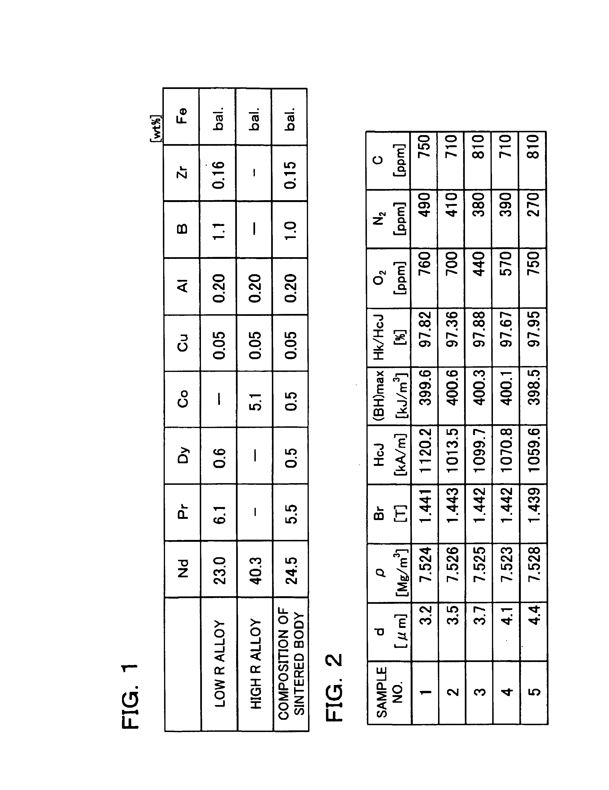
[0120]Master alloys (a low R alloy and a high R alloy) with compositions shown in FIG. 1 were prepared by the strip casting method.

[0121]A hydrogen crushing treatment was carried out on each of the obtained master alloys, in which after hydrogen was absorbed at room temperature, dehydrogenation was carried out thereon at 600° C. for 1 hour in an Ar atmosphere.

[0122]In order to obtain high magnetic properties, the amount of oxygen contained in a sintered body was controlled to 1,000 ppm or less in Experiment example 1. On this account, the atmosphere was controlled at an oxygen concentration of 100 ppm or less throughout processes, from a hydrogen crushing treatment (recovery after a crushing process) to sintering (input into a sintering furnace) (this condition was also applied in the following Experiment examples 2 to 11).

[0123]Generally, two-step crushing is carried out, which includes rough crushing and pulverizing. However, the crushing was omitted in Experim...

experiment example 2

[0132]Three types of permanent magnets (samples 6 to 8) were obtained in the same manner as in Experiment example 1 with the exceptions that the master alloys with the compositions shown in FIG. 6 were used and that the amount of oxygen contained in the final sintered body was fluctuated by controlling the amount of oxygen contained in crushing gas (nitrogen) during the preparation of fine powders. The magnetic properties of the obtained permanent magnets were measured in the same manner as in Experiment example 1. The results are shown in FIG. 7. It is noted that Ts in FIG. 7 represents a sintering temperature and other symbols have the same meanings as in FIG. 2.

[0133]As shown in FIG. 7, it is found that all the permanent magnets of samples 6 to 8 have a residual flux density of 1.4 T or more, a coercive force of approximately 1,000 kA / m, and a high maximum energy product of approximately 400 kJ / m3.

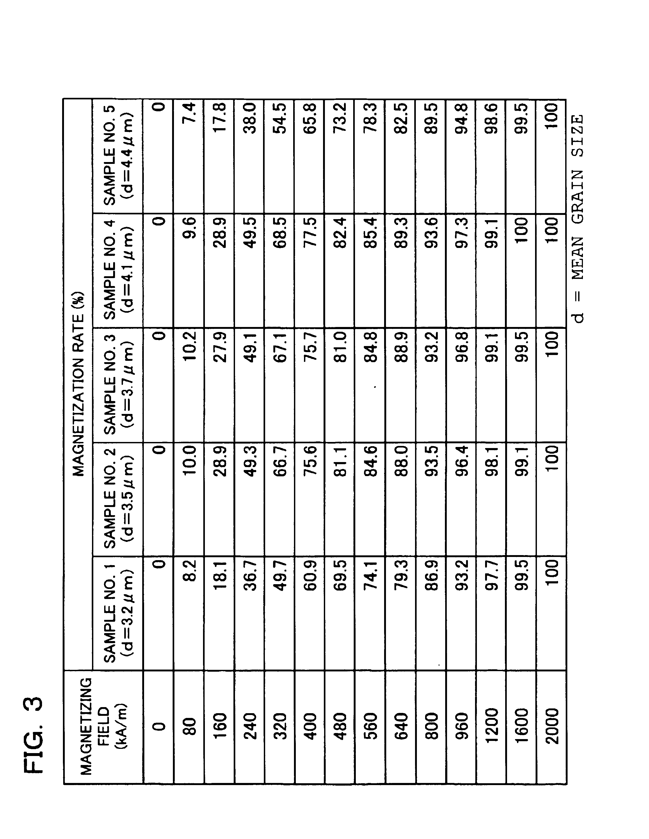
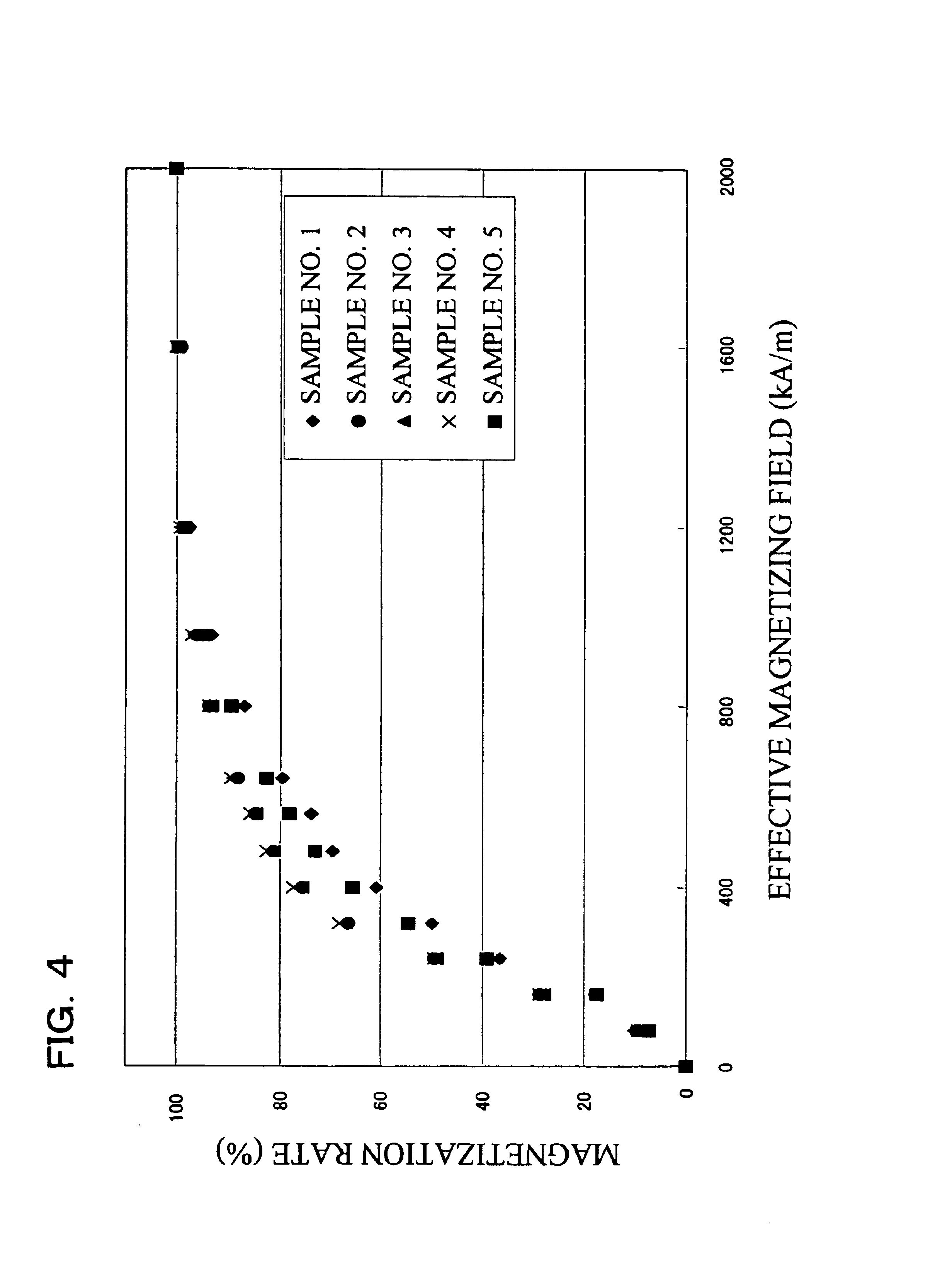
[0134]Subsequently, the permanent magnets of samples 6 to 8 were measured in terms ...


PUM

PropertyMeasurementUnit
Grain sizeaaaaaaaaaa

Abstract

An R-T-B system rare earth permanent is provided, which comprises a sintered body comprising: an R2T14B phase (wherein R represents one or more rare earth elements (providing that the rare earth elements include Y) and T represents one or more transition metal elements essentially containing Fe, or Fe and Co) as a main phase; and a grain boundary phase containing a higher amount of R than the above main phase, wherein, when Pc (permeance coefficient) is 2, if a total flux is defined as f1 under the application of an effective magnetic field of 240 kA/m (providing that an effective magnetic field=an applied magnetic field−a demagnetizing field, and each value of them is absolute value), if a total flux is defined as f2 under the application of an effective magnetic field of 800 kA/m, and if a total flux is defined as f3 under the application of an effective magnetic field of 2,000 kA/m, a magnetization rate a (=f1/f3×100) is 40% or more, and a magnetization rate b (=f2/f3×100) is 90% or more.

Description

BACKGROUND OF THE INVENTION[0001]1. Field of the Invention[0002]The present invention relates to an R-T-B system rare earth permanent magnet (wherein R represents one or more rare earth elements (providing that the rare earth elements include Y), and T represents one or more transition metal elements essentially comprising Fe, or Fe and Co), and especially relates to an R-T-B system rare earth permanent magnet with high magnetizability.[0003]2. Description of the Related Art[0004]Among rare earth permanent magnets, an R-T-B system rare earth permanent magnet has been adopted in various types of electric equipment for the reasons that its magnetic properties are excellent and that its main component Nd is abundant as a source and relatively inexpensive.[0005]Research and development directed towards the improvement of the magnetic properties of the R-T-B system rare earth permanent magnet, more specifically, the improvement of a residual flux density, a coercive force and a maximum e...

Claims


Application Information

Patent Timeline
IPC IPC(8): H01F1/053H01F1/057
CPCH01F1/0577
Inventor HIDAKA, TETSUYASAKAMOTO, KAZUYASATO, KAZUOOKADA, HIRONARI
Owner TDK CORPARATION
Why Eureka
Try Eureka