Dynamic software code instrumentation method and system

a software code and instrumentation method technology, applied in the field of software analysis, can solve the problems of not being easily usable in connection with processors not originally manufactured with integrated debugging capabilities, increasing the number of executable lines of code, and increasing the size of code in proportion to the number of functions

Inactive Publication Date: 2003-10-30
WIND RIVER SYSTEMS
View PDF23 Cites 45 Cited by
  • Summary
  • Abstract
  • Description
  • Claims
  • Application Information

AI Technical Summary

Problems solved by technology

A drawback of these approaches, however, is that they are not readily usable in connection with processors not originally manufactured with integrated debugging capabilities.
Disadvantageously, this approach is integrated into the processor rather than being suitable for use with processors not originally manufactured with such integrated systems.
A drawback of this approach, however, is that discrete tag statements, which tend to disadvantageously increase the number of executable lines of the code, must be included within the source code.
These discrete tags disadvantageously increase the size of the code in proportion to the number of functions instrumented.
Moreover, although the tags may be monitored, the code continues to be executed within cache, and thus is not directly observable.
The misalignment instruction causes a fault prior to actual execution thereof.

Method used


Image

  • Dynamic software code instrumentation method and system
  • Dynamic software code instrumentation method and system
  • Dynamic software code instrumentation method and system

Examples


example 1

[0067] This example describes the "code insertion" instrumentation behavior of step 3 of Table 4 above. This example examined a function such as "add values reference" that receives pointers to structures and adds their values together returning them in a global structure. In the event this function appears to be operating incorrectly, the "patch" or "code insertion" feature (step 3) of Table 4 may be used to dynamically insert code to monitor (e.g., by a "printf" statement 97 that outputs the values to buffer 103), or code to alter behavior (such as forcing a known value into a variable). For simplicity, in this example, "add_values_reference" performs only an assignment. Sample code used in this Example 1 is shown as "Sample Code Listing 1" hereinbelow.

7 Sample Code Listing 1: int add_values_reference(MY-_STRUCT *structure1, MY_STRUCT *structure2) { global_struct_2.integer_value = structure1->integer_value + structure2->integer_value; global_struct_2.char_value = structure1->char_...

example 2

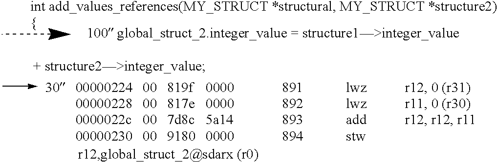
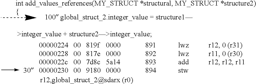
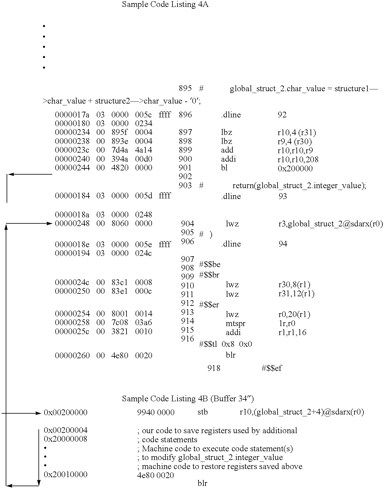
[0071] The sample code of Example 1 may be instrumented to force a value (Step 5 of Table 4 and the steps of Table 5 hereinabove) to a variable after it was modified by normal program flow. In this example, step 2 of Table 5 adds a "global_struct.sub.--2.integer_value=10" to force "global_struct.sub.--2.integer_" to a value of 10 after it was modified by normal program flow. This generates a change (relative to the Sample Code Listing 1) in the machine code in memory at line 244, as shown in Sample Code Listing 4A below. As shown, the original instruction at line 244 has been replaced with a program flow change instruction 30'" branching 90' (FIG. 14) execution to the scratchpad buffer 34" shown in Sample Code Listing 4B. The code in the buffer 34" effects the desired data manipulation (i.e., forcing the value to 10), and branches execution back to line 248. Line 248 line is thus effectively changed since this instruction places the forced value into register r3 as shown.

10 3

[0072] ...

example 3

[0074] In this example, the "data capture" instrumentation behavior (e.g., function 3 of Table 4) is described with reference to the functions "reference_function" and "value_function". These functions both use the global parameter `global_struct.sub.--1`, shown with arrows "-->" in Sample Code Listing 5A below.

11 Sample Code Listing 5A Original source code: MY_STRUCT reference_function(int *parameter1, char *parameter2) { MY_STRUCT local_struct; local_struct.integer_value = *parameter1; local_struct.char_value = *parameter2; 4 global_struct_1.integer_value = *parameter1; return(local_struct); } MY_STRUCT value_function(int parameter1, char parameter2) { MY_STRUCT local_struct; local_struct.integer_value = parameter1; local_struct.char_value = parameter2; 5 global_struct_1 = local_struct; return (local_struct); }

[0075] In order to capture all modifications to "global_struct.sub.--1", instrumentation module 12' analyzes the symbol table (e.g., generated during compiling the original ...


PUM


Abstract

A method and system of monitoring code after being compiled or assembled is provided. Software code instructions, such as a function preamble and / or a data manipulation instruction, are identified using debug information and then dynamically replaced with an instruction that will branch execution to a scratchpad buffer. A routine is inserted into the scratchpad buffer, and includes instruction(s) to generate output to a trace buffer. Subsequent instructions in the scratchpad may execute the replaced instruction(s) and branch back to the address of the program code immediately following the original address of the replaced instruction.

Description

[0001] This application is a continuation-in-part of U.S. patent application Ser. No. 09 / 310,441, entitled Dynamic Software Code Instrumentation Method and System, filed May 12, 1999.BACKGROUND OF THE INVENTION 1. Field of the Invention[0002] This invention relates to software analysis, and more particularly to a method and apparatus for dynamically instrumenting software executing on embedded systems for analysis thereof.[0003] 2. Background Information[0004] A wide variety of hardware and / or software systems for generating an exception to debug, test and / or emulate a target processor are known in the art. Such systems provide their functionality using many disparate technologies.[0005] For example, U.S. Pat. No. 5,560,036 to Yoshida; U.S. Pat. No. 5,737,516 to Circello et al.; U.S. Pat. No. 5,530,804 to Edgington et al., (the '804 patent); and U.S. Pat. No. 5,493,664 to Doi, all disclose processors having hardware or software integrated therein which facilitates debugging. A drawb...

Claims


Application Information

Patent Timeline
Patent Type & Authority Applications(United States)
IPC IPC(8): G06F11/34G06F11/36
CPCG06F11/3466G06F11/3664G06F11/3644G06F11/3636
Inventor MADSEN, KENNETH E.LEE, DERSANGDAWSON, PETER S.
Owner WIND RIVER SYSTEMS
Why Eureka
Try Eureka