Stent mounting device and a method of using the same to coat a stent

a technology of mounting device and stent, which is applied in the direction of prosthesis, blood vessels, packaging foodstuffs, etc., can solve the problems of removing some of the needed coating from the stent, causing other defects, and affecting the effect of stent treatmen

Inactive Publication Date: 2003-11-06
ABBOTT CARDIOVASCULAR
View PDF44 Cites 139 Cited by
  • Summary
  • Abstract
  • Description
  • Claims
  • Application Information

AI Technical Summary

Benefits of technology

[0013] The mounting assembly can apply a force on a first end of the stent in a first direction and an opposite force on a second end of the stent in a second direction. Accordingly, the mounting assembly prevents any significant movement of the stent.
[0014] In one embodiment, the means for applying the forces to the first and second ends of the stent are defined by a pair of members having inwardly tapered ends that penetrate at least partially in the first and second ends of the stent and are in contact with an inner rim of the first and second ends of the stent. In another embodiment, one of the inwardly tapered ends can be incrementally moved closer to the other inwardly tapered end so as to increase the forces applied to the first and second ends of the stent.
[0015] The present invention also provides a method of coating a stent. The method includes mounting a stent on a support assembly and forming a coating on the stent. The support assembly does not contact a significant portion of the inner surface of the stent. In one embodiment, the act of mounting includes positioning one end of the stent over a coned end of a first member, positioning a coned end of a second member within the opposing end of the stent, and reducing the distance between the coned ends such that the stent is securely pinched between the coned ends.

Problems solved by technology

A shortcoming of the above-described method of medicating a stent is the potential for coating defects.
While some coating defects can be minimized by adjusting the coating parameters, other defects occur due to the nature of the interface between the stent and the apparatus with which the stent is supported during the coating process.
Upon the removal of the coated stent from the supporting apparatus, the excess coating may stick to the apparatus, thereby removing some of the needed coating from the stent and leaving bare areas.
Over or under application of support force can lead to coating defects, such as non-uniformity of the coating thickness.
ight. Excessive application of the polymer can, however, cause coating de

Method used


Image

  • Stent mounting device and a method of using the same to coat a stent
  • Stent mounting device and a method of using the same to coat a stent
  • Stent mounting device and a method of using the same to coat a stent

Examples


Embodiment Construction

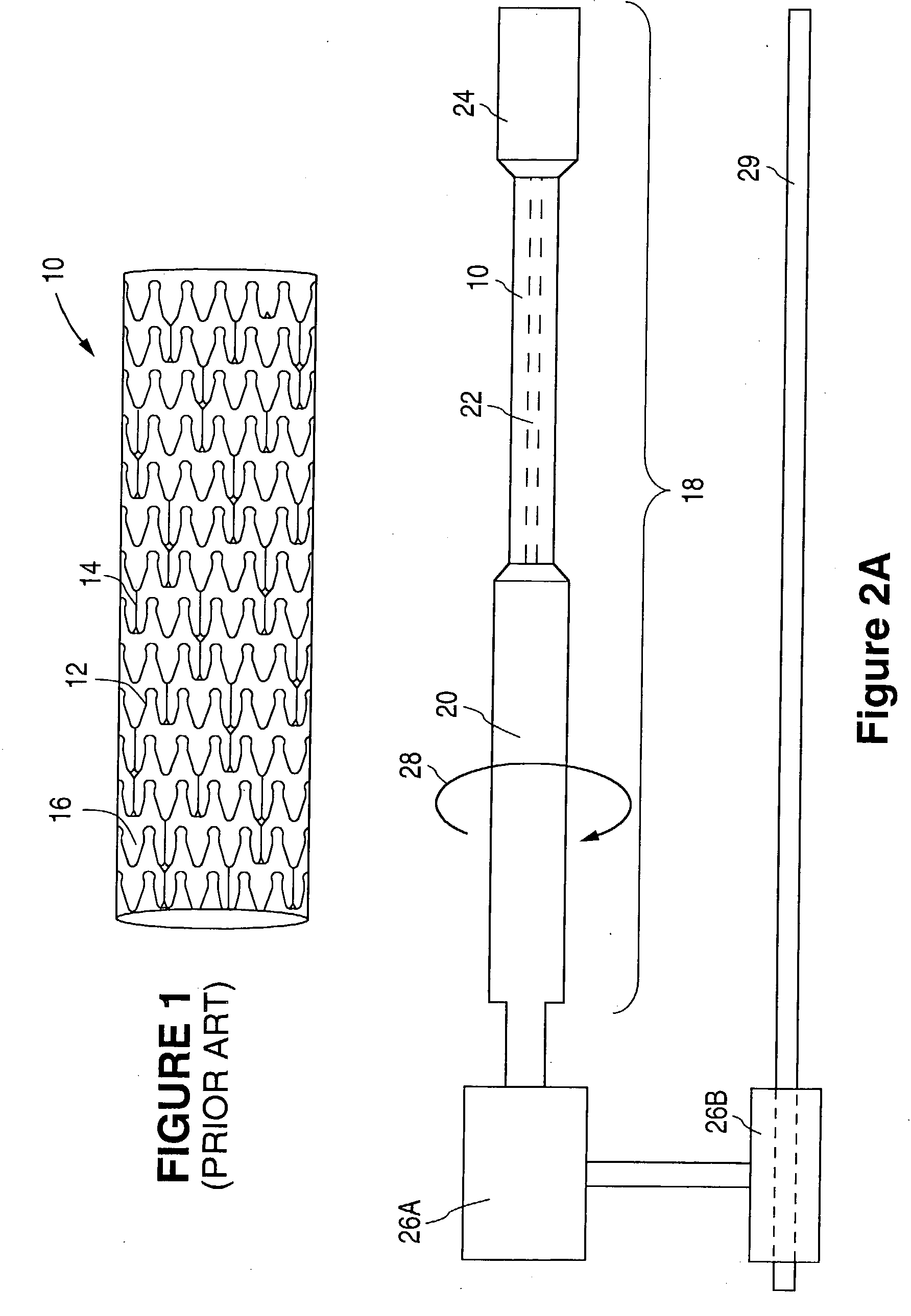
[0037] FIG. 4A illustrates uncoated struts of a Multi-Link SOLO stent (available from Guidant Corporation). By contrast, FIG. 4B illustrates struts of a Multi-Link SOLO stent that was spray-coated to yield a uniform coating on the surfaces of the stent struts in accordance with the protocol set forth below.

[0038] Eighteen 3.0 mm Multi-Link SOLO stents were spray-coated while supported by mounting assembly 18 of the present invention. The stents had been previously passivated to remove surface contaminants, such as exogenous iron compounds, by chemically treating the stents, for example with an acid solution.

[0039] A 0.1% heparin solution was prepared by dissolving 0.5 g of Duraflo II heparin powder (a heparin derivative offered by Baxter International) with 500 ml of Genesolv 2004 solvent (obtained from Allied Signal, Ontario, Canada). A 0.5%. heparin solution was prepared by dissolving 2.5 g of Duraflo II heparin powder with 500 ml of Genesolv 2004 solvent.

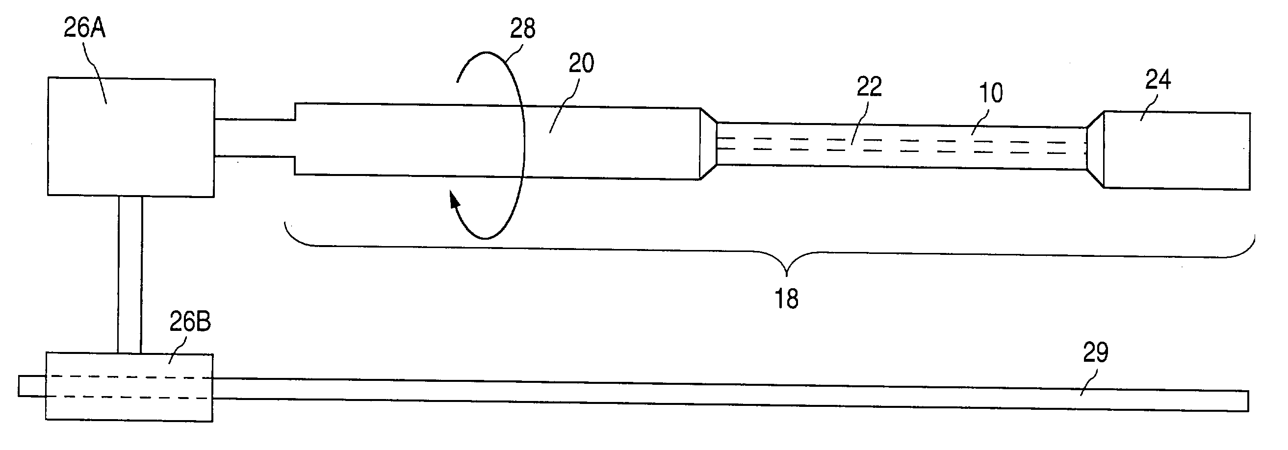
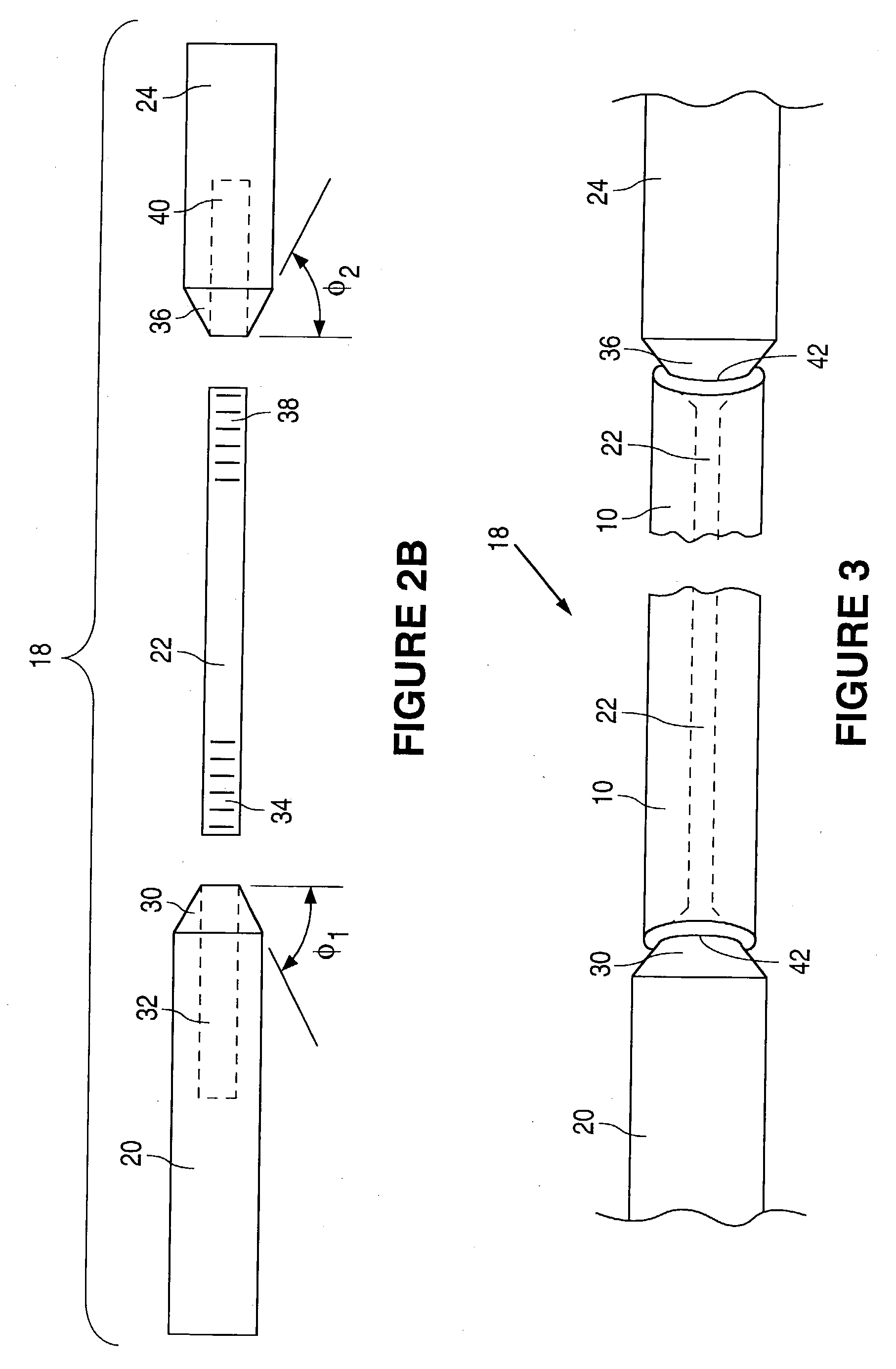
[0040] Support member 20 ...


PUM

PropertyMeasurementUnit
angle φ1aaaaaaaaaa
angle φ1aaaaaaaaaa
angle φ1aaaaaaaaaa

Abstract

A stent mounting device and a method of coating a stent using the device are provided.

Description

[0001] 1. Field of the Invention[0002] This invention relates to a stent mounting device and a method of coating a stent using the device.[0003] 2. Description of the Background[0004] Blood vessel occlusions are commonly treated by mechanically enhancing blood flow in the affected vessels, such as by employing a stent. Stents act as scaffoldings, functioning to physically hold open and, if desired, to expand the wall of the passageway. Typically stents are capable of being compressed, so that they can be inserted through small cavities via catheters, and then expanded to a larger diameter once they are at the desired location. Examples in the patent literature disclosing stents include U.S. Pat. No. 4,733,665 issued to Palmaz, U.S. Pat. No. 4,800,882 issued to Gianturco, and U.S. Pat. No. 4,886,062 issued to Wiktor.[0005] FIG. 1 illustrates a conventional stent 10 formed from a plurality of rigid but resiliently flexible struts 12 that are arranged in a sinusoidal-like configuration...

Claims


Application Information

Patent Timeline
Patent Type & Authority Applications(United States)
IPC IPC(8): A61F2/00A61F2/06A61F2/90
CPCA61F2/91A61F2/915A61F2230/0013A61F2002/91566A61F2250/0067A61F2002/91533
Inventor VILLAREAL, PLARIDEL K.
Owner ABBOTT CARDIOVASCULAR
Why Eureka
Try Eureka