
Cathode ray tube

a cathode ray tube and tube body technology, applied in discharge tube/lamp details, non-electron-emitting shielding screens, picture reproducers, etc., can solve the problems of reducing picture quality, unable to provide optimal initial current values, and not providing specific disclosure of optimal initial current values

Inactive Publication Date: 2003-11-20
SAMSUNG SDI CO LTD
View PDF2 Cites 2 Cited by
  • Summary
  • Abstract
  • Description
  • Claims
  • Application Information

AI Technical Summary

Benefits of technology

[0011] The present invention provides a cathode ray tube that improves the ability to restore metal parts to a demagnetized state.

Problems solved by technology

That is, mis-landing of the electrons beams occurs, and this reduces picture quality.
However, with the art described above, no such specific disclosure of an optimal initial current value is provided.
Accordingly, quick and sufficient demagnetization is not possible, thereby making actual application impractical.

Method used


Image

  • Cathode ray tube
  • Cathode ray tube
  • Cathode ray tube

Examples


Embodiment Construction

[0034] While the present invention will be described more fully hereinafter with reference to the accompanying drawings, in which details of the present invention are shown, it is to be understood at the outset of the description which follows that persons of skill in the appropriate arts may modify the invention here described while still achieving the favorable results of this invention. Accordingly, the description of the best mode contemplated of carrying out the invention, which follows, is to be understood as being a broad, teaching disclosure directed to persons of skill in the appropriate arts, and not as limiting upon the present invention.

[0035] Illustrative embodiments of the best mode of carrying out the invention are described below. In the interest of clarity, not all features of an actual implementation are described. In the following description, well-known functions, constructions, and configurations are not described in detail since they could obscure the invention...


PUM


Abstract

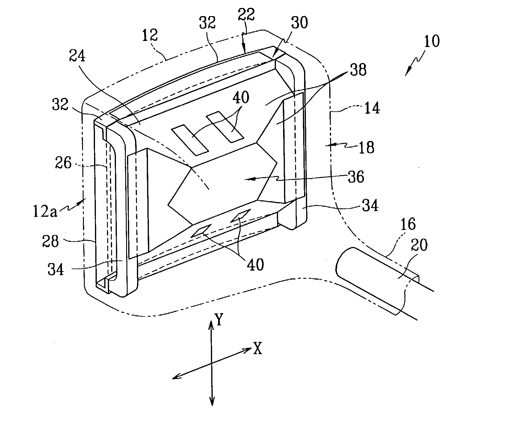
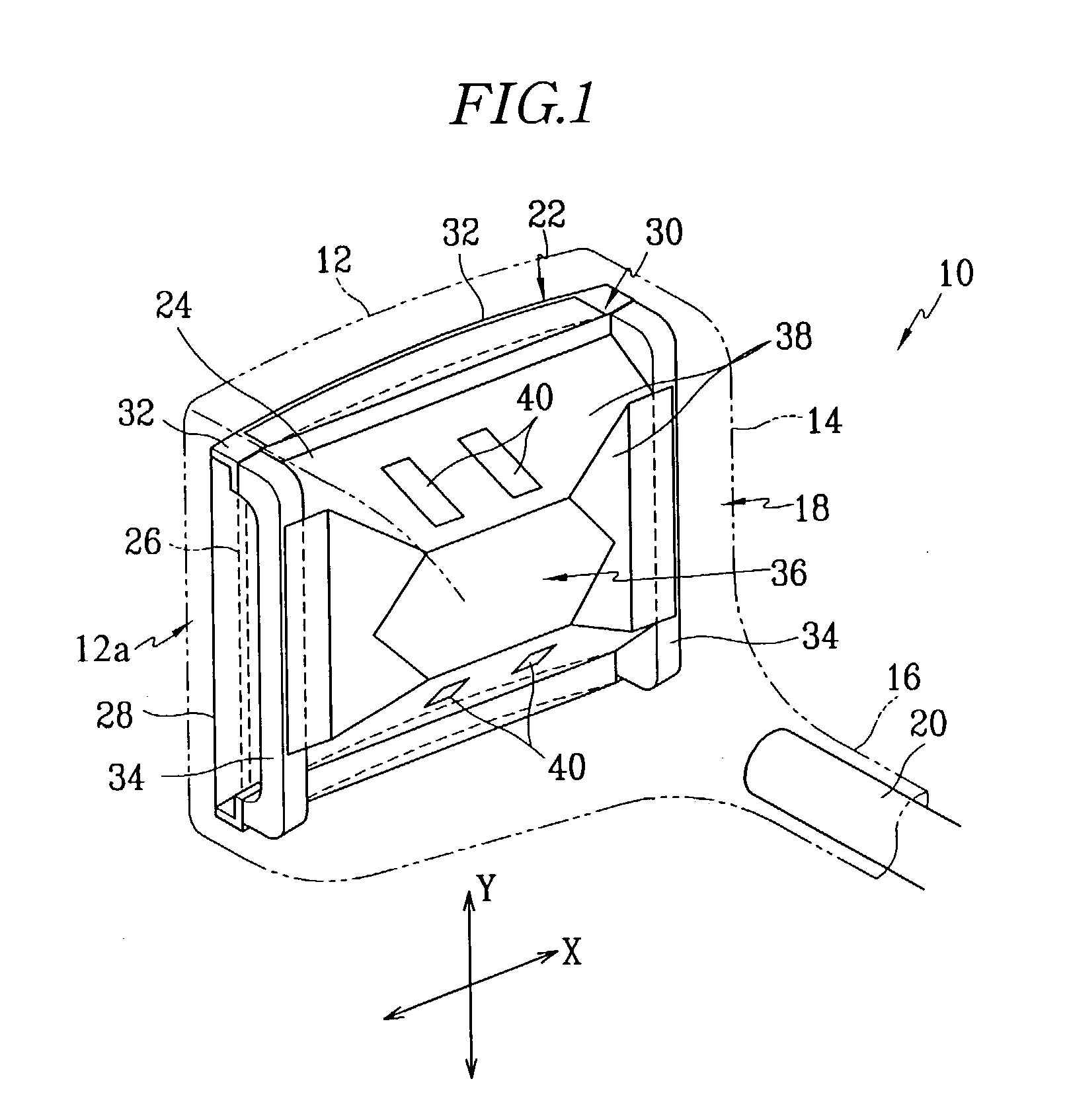
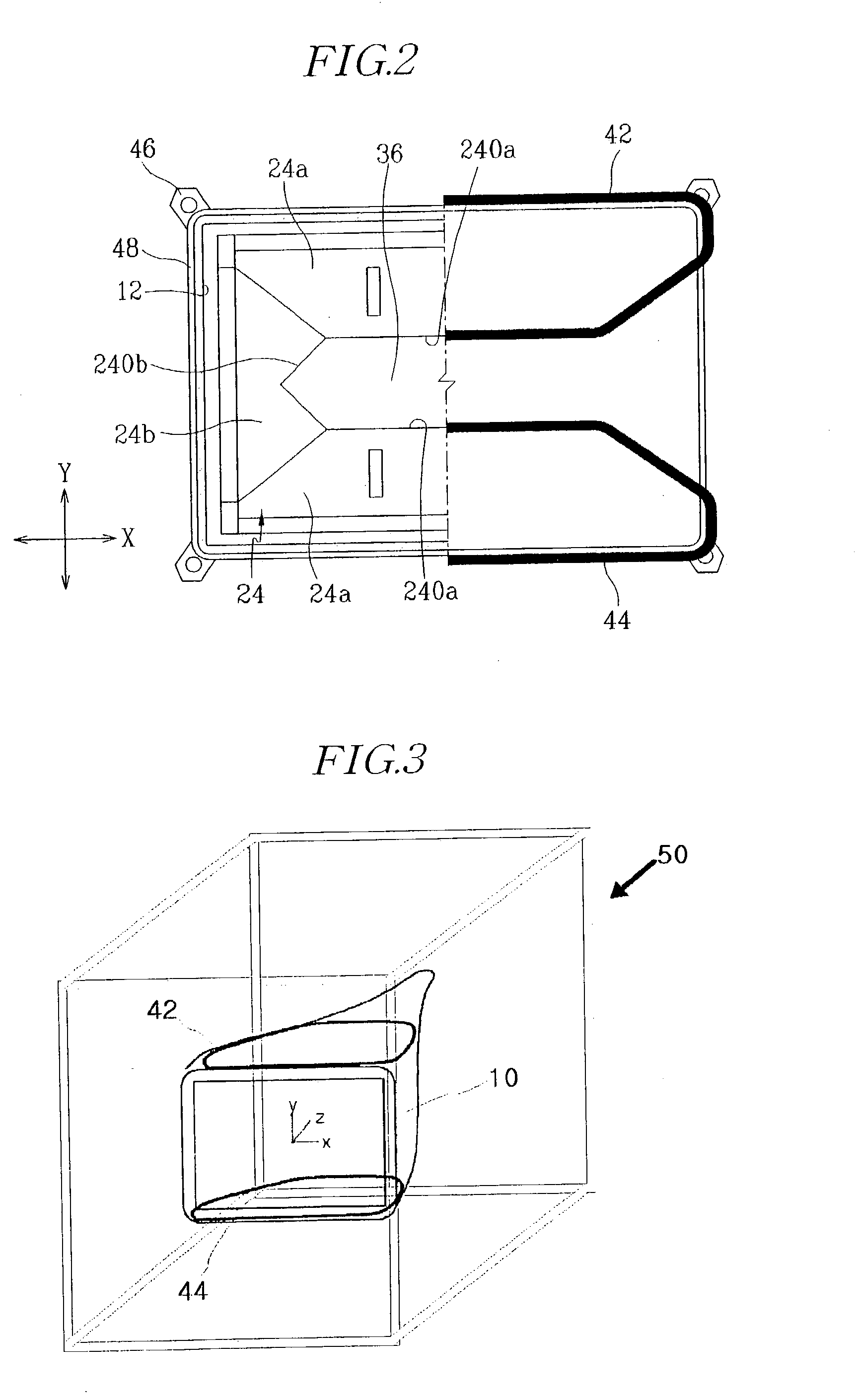
A cathode ray tube includes an evacuated envelope including a face panel, a funnel, and a neck; a color selection apparatus mounted inwardly from the face panel; an electron gun mounted within the neck; a magnetic shield mounted connected to the color selection apparatus; and degaussing coils mounted to an outer surface of the evacuated envelope. A degaussing current flowing to the degaussing coils has a waveform such that a line connecting a peak A from where a maximum current value first starts to decrease and a peak G of a sixth cycle is a functional curve of a second degree or greater.

Description

CLAIM OF PRIORITY[0001] This application makes reference to, incorporates the same herein, and claims all benefits accruing under 35 U.S.C .sctn. 119 from an application entitled CATHODE RAY TUBE filed with the Korean Intellectual Property Office on May 14, 2002 and there duly assigned Serial No. 2002-26489.[0002] 1. Technical Field[0003] The present invention relates to a cathode ray tube, and more particularly, to a cathode ray tube that uses a degaussing coil for demagnetizing metal parts in the cathode ray tube such as a color selection apparatus and an inner shield.[0004] 2. Related Art[0005] Metal parts are typically found in a cathode ray tube (CRT). Such metal parts include (a) a color selection apparatus comprised of a shadow mask that has a plurality of apertures for performing color separation of three electron beams, which are emitted from an electron gun, to corresponding red, green, blue (R,G,B) phosphors of a phosphor screen, and a mask frame for fixedly supporting th...

Claims


Application Information

Patent Timeline
Patent Type & Authority Applications(United States)
IPC IPC(8): H01J29/00H04N9/29
CPCH04N9/29H01J29/003
Inventor KIM, SEONG-SEOBWOO, TOK-CHIN
Owner SAMSUNG SDI CO LTD
Learn More