Method of Determining Boundary Interface Changes in a Natural Resource Deposit

a natural resource and boundary interface technology, applied in the field of determining timedependent boundary interface changes in natural resource deposits, can solve the problems of reducing recovery efficiency and identification of boundary or interfaces

Inactive Publication Date: 2003-11-27
LOCKHEED MARTIN CORP
View PDF4 Cites 29 Cited by
  • Summary
  • Abstract
  • Description
  • Claims
  • Application Information

AI Technical Summary

Benefits of technology

0017] The present invention provides a method of determining boundary interface changes in a natural resource deposit, such as a sub-surface oil reservoir, using time-lapse gravity gradient measurements and simulated annealing optimization to find the global minimum within the solution space that best represents the observed values. A pluralilty of observations points is established relative to the natural resource deposit and gravity gradiometric measurements are taken at each observation point to provide a first observed data set. Thereafter and after the lapse of a period of time, a second set of measurements is similarly taken to provide a second observed data set and the time-lapse data set representative of the difference between the first and subsequent observed data sets. A

Problems solved by technology

One problem associated with water, steam, or gas driveout techniques is the identification of the boundary or interface between the driveout fluid and the crude oil.
The pressurized driveout fluid sometimes forms low-impedance channels, known as 'theft' zones, through which the pressurized fluid "punche

Method used


Image

  • Method of Determining Boundary Interface Changes in a Natural Resource Deposit
  • Method of Determining Boundary Interface Changes in a Natural Resource Deposit
  • Method of Determining Boundary Interface Changes in a Natural Resource Deposit

Examples


Embodiment Construction

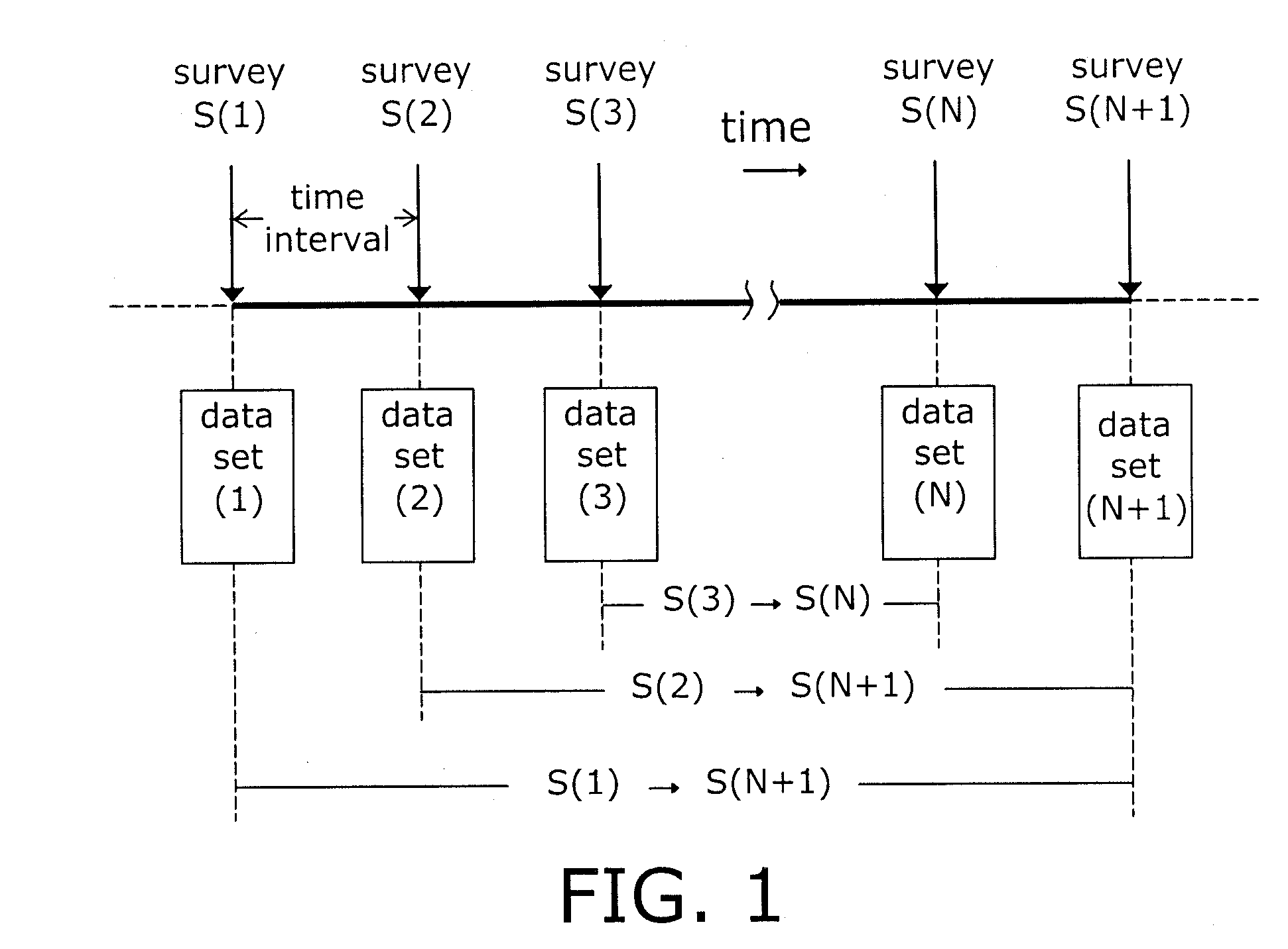
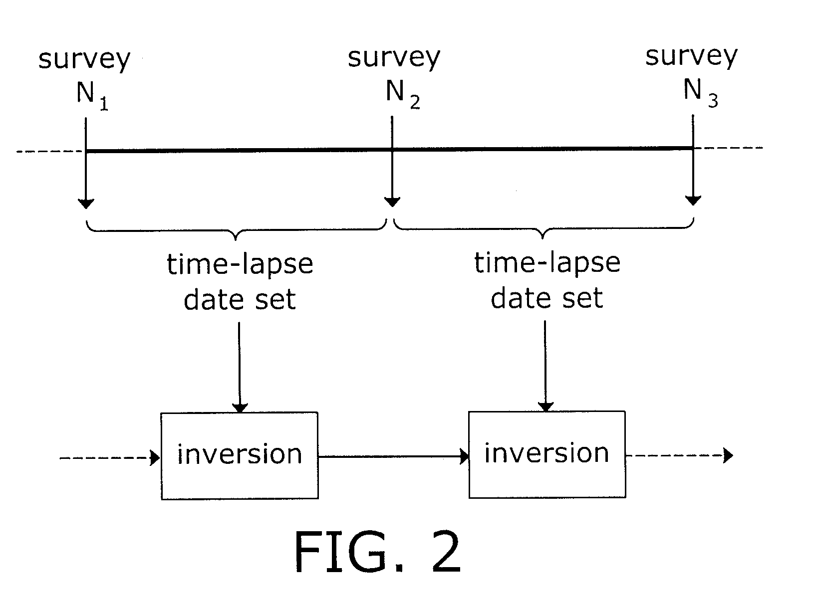
[0029] In the preferred embodiment, the present invention is utilized in the context of plural time-separated sets of gravity gradiometer measurements taken relative to an oil reservoir undergoing secondary oil recovery consequent to the injection of steam, hot water, and / or other fluids via injection wells to cause the injected fluid to drive the oil toward and to an output well or wells. In general, a number of observation points are established on the oil field under survey; it is important that the location of the observation points be fixed for the period of the first and subsequent surveys. A gravity gradiometer, as described in the aforementioned commonly assigned U.S. Patent 6,152,226 (incorporated herein by reference), is located at a first observation point. The gravity gradiometer then takes data at the observation station for some period of time sufficient to insure the reliability of gravity gradient data. Thereafter, the gravity gradiometer is moved to the next success...


PUM


Abstract

Abstract of Disclosure A method of determining changes in the boundary interface in a sub-surface oil reservoir between the to-be-recovered oil and a driveout fluid, such as steam, uses time-displaced gravity gradient measurements to provide an indication of the changes in the gravity gradient over time. The measured data are subject to simulated annealing optimization to find the global minimum that best represents the observed values within the solution space. The optimization process includes establishing an appropriately constrained model of the oil reservoir and a quantized set of mathematically related parameters that define the model. Successive models are perturbed and evaluated from a figure of merit standpoint until a global minimum that best describes the measured time-lapse data is found.

Description

Cross Reference to Related Applications[0001] This application claims the benefit of the filing date of co-pending U.S. Provisional Patent Application No. 60 / 197,618 filed April 14, 2000 by the applicants herein.Background of Invention[0002] The present invention relates to a method of determining time-dependent boundary interface changes in a natural resource deposit and, more particularly, to a method by which measurements of the gravity gradient in the area of a natural resource deposit, such as a petroloeum reservoir, can provide information as to reservoir density changes.[0003] Oil and natural gas hydrocarbon reservoirs form as a consequence of the transformation of organic matter into various types of hydrocarbon materials, including coals, tars, oils, and natural gas. It is believed that oil and gas reservoirs form as lighter hydrocarbon molecules percolate toward the surface of the earth until they are trapped in a relatively permeable layer beneath a relatively impermeable...

Claims


Application Information

Patent Timeline
IPC IPC(8): G01V7/00G01V7/06G06F19/00
CPCG01V7/06
Inventor FELDMAN , WALTER K.MAZZOLA , DANIEL P.
Owner LOCKHEED MARTIN CORP
Why Eureka
Try Eureka