

Telescope sparse array not requiring the use of laser interferometry
a technology of laser interferometry and telescopes, which is applied in the field of telescope sparse arrays that do not require the use of laser interferometry, can solve the problems of difficult compensation, nightmares (or impossible) at best, and little gain in extrasolar earthlike planet imaging, and achieve the effect of rapid strehle ratio maximization and high resolution
Inactive Publication Date: 2003-12-11
MAKER DAVID JOEL
View PDF9 Cites 27 Cited by
- Summary
- Abstract
- Description
- Claims
- Application Information
AI Technical Summary
Benefits of technology
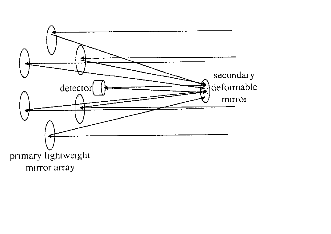
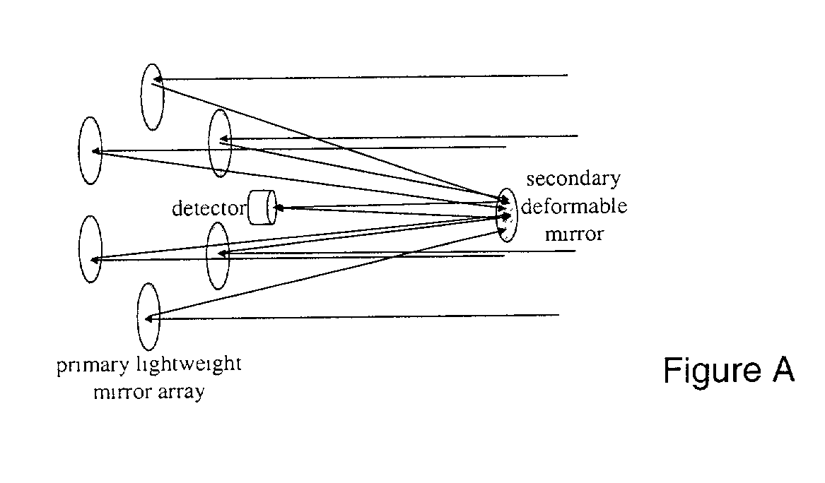
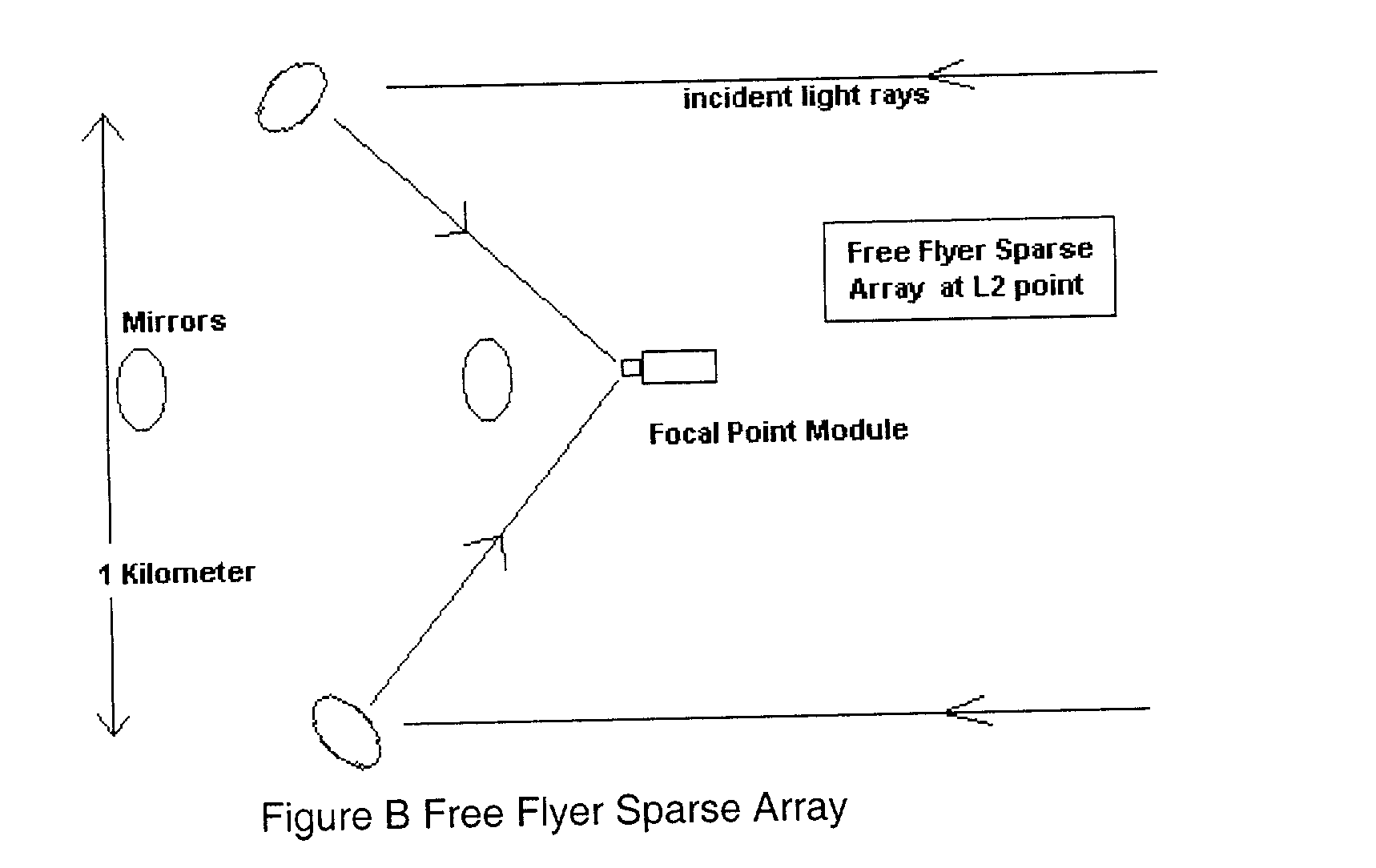
[0061] With this invention we just need (actuated) flats on a parabola with a central focal point module. The mirrors will be on the order of a kilometer distant from that module so that tip tilt can be sensed (and then controlled) by sensors on the module that also detect beam pointing. The actual (high SNR) star the planet is orbiting can be used for rapid Strehle ratio maximization so that NO laser interferometry is needed at all. Fine mirror control can be done by variable reflectivity of the backside of the mirrors. The mirrors can be placed at L2 so that their orbits are all the same. A lot of this multi space craft control has already been accomplished with the ESA "Cluster".Thus it is possible to build an extremely high resolution, multi kilometer baseline visible light TPF that operates without the use of laser interferometry.
Problems solved by technology
One is the conservative, filled aperture approach which promises only about a 2 or 3 times increase in resolution over the NGST, so very little is gained in terms of extrasolar earthlike planet imaging.
In NGST research it was discovered that tip tilt sensitivity is approximately 7 times greater than piston phase sensitivity, therefore correspondingly difficult to compensate for (Motion of the mirror along the plane of the parabola is not nearly as critical).
Laser interferometric control must be done at 6 DOF to compensate for tip tilt situation and would be a nightmare (or impossible) at best for a group of free flying mirrors.
In other words, the motions of the mirrors, parallel to the optical path, is the main contributor to image distortion.
Strehl ratio maximization is also a critical issue.
Refractors are used since obstructions in reflecting telescope optical paths (e.g., secondary mirror supports) cause many complications in the deconvolution process.
However, motions of one mirror edge, relative to another on the same mirror, do require about {fraction (1 / 10)} wave accuracy and do cause a large degradation in the image of a point source.
Fast primary mirrors are very sensitive to collimation errors.
In any case, this kind of pointing error is required for imaging purposes.
The irony is that this solution would not be possible with much shorter focal length arrays since the diameter, x, would be proportionally smaller, thereby increasing the difficulty of measurement.
Level of Difficulty of Wavefront Shape Control
But in that case, micrometeoroid degradation is large (especially around 800 km), and mirrors would have to be replaced periodically (.about.2 years).
Also, orbital velocities of these distant mirror elements would be noticeably different (given Keplerian motion) for low orbit sparse arrays, putting much more severe demands on station keeping than there would be at a lagrangian point.
The laser interferometry (especially tip tilt correction) you will need here may prove to be really difficult(or impossible?) so a method like this one is needed to fall back on.
Method used
View moreImage
Smart ImageViewing Examples

Examples
Embodiment Construction
[0062] There are 6 3 meter thin freeflying mirrors with actuation at a kilometer from the focal point module in that sparse array. The tiptilt is controled by sensors at the focal point module that control beam pointing. The piston control is done by rapid strehle ratio maximization on the star that the planet is orbiting. Fine mirror control can be done by variable reflectivity of the backside of the mirrors. The mirrors can be placed at L2 so that their orbits are all the same.
Login to View More PUM
 Abstract
Recent schemes have been accepted by NASA in its TPF program for simple sparse arrays. But these methods require a great deal of interferometric control of tip tilt and other motion. But with this invention we just need (actuated) flats on a parabola with a central focal point module. The mirrors will be on the order of a kilometer distant from that module so that tip tilt can be sensed (and then controled) by sensors on the module that also detect beam pointing. The actual (high SNR) star the planet is orbiting can be used for rapid Strehle ratio maximization so that NO laser interferometry is needed at all. Fine mirror control can be done by variable reflectivity of the backside of the mirrors. The mirrors can be placed at L2 so that their orbits are all the same. A lot of this multi space craft control has already been accomplished with the ESA "Cluster".
Description
[0001] Not applicableStatement Regarding Federally Sponsored Research or Development[0002] There was no Federally sponsored research or development involved in this patent.BACKGROUND OF INVENTION[0003] Two types of approaches have been recently accepted by NASA for its Terrestrial Planet Finder (TPF) program. One is the conservative, filled aperture approach which promises only about a 2 or 3 times increase in resolution over the NGST, so very little is gained in terms of extrasolar earthlike planet imaging. The second TPF method (using laser interferometry) involves a great deal of laser interferometric control of tip tilt and other motion for physically connected, deep dish (low F), hard to transport, large aberration mirrors and promises perhaps a factor of 10 increas in resolution thus with little gain for the effort and a nightmarishly complex laser interferometric control required. In any case a very large, kilometer wide or wider sparse array, is needed for imaging and resolv...
Claims
Login to View More Application Information
Patent Timeline
 Patent Type & AuthorityApplications(United States)
IPC IPC(8): G02B23/02
CPCG02B23/02
InventorMAKER, DAVID JOEL
OwnerMAKER DAVID JOEL