Method and apparatus for forming a bent or folded edge rim of a self-supporting thin-walled molded component

a self-supporting, thin-walled technology, applied in the direction of baking, paper/cardboard containers, containers, etc., can solve the problems of high energy consumption of known methods and apparatuses, difficult selection of decorative cover stock materials, and stiff finished free edge rims of finished molded components

Inactive Publication Date: 2003-12-18
R S TECHN
View PDF7 Cites 13 Cited by
  • Summary
  • Abstract
  • Description
  • Claims
  • Application Information

AI Technical Summary

Problems solved by technology

For example, the known methods and apparatuses operate with a high energy consumption.
Also, whenever edge rim parts are pressed together during the edge folding or beading process, there is always the danger of the undesired result, that the finished free edge rim of the finished molded component will be very stiff due to the doubling, folding, and compaction of the material at the area of the fold.
Furthermore, in the known methods and apparatuses, the selection of useable decorative cover stock materials is often quite limited, due to the particularities of the known methods and apparatuses.
For example, cover stock materials with a particular surface texture or the like are not suitable, because the surface texture will be destroyed, damaged, or interfered with during the edge folding and pressing operations.
Also, the finished quality of the folded or beaded and pressed edge rims is often unsatisfactory, for example, due to the bunching, compaction, and / or doubling of the folded material along the folded edge of the finished edge rim.

Method used


Image

  • Method and apparatus for forming a bent or folded edge rim of a self-supporting thin-walled molded component
  • Method and apparatus for forming a bent or folded edge rim of a self-supporting thin-walled molded component
  • Method and apparatus for forming a bent or folded edge rim of a self-supporting thin-walled molded component

Examples


Embodiment Construction

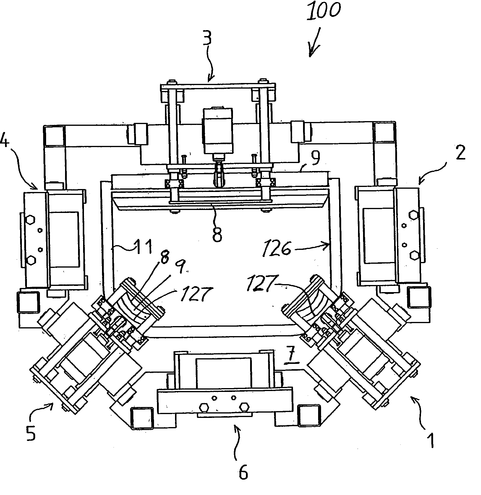
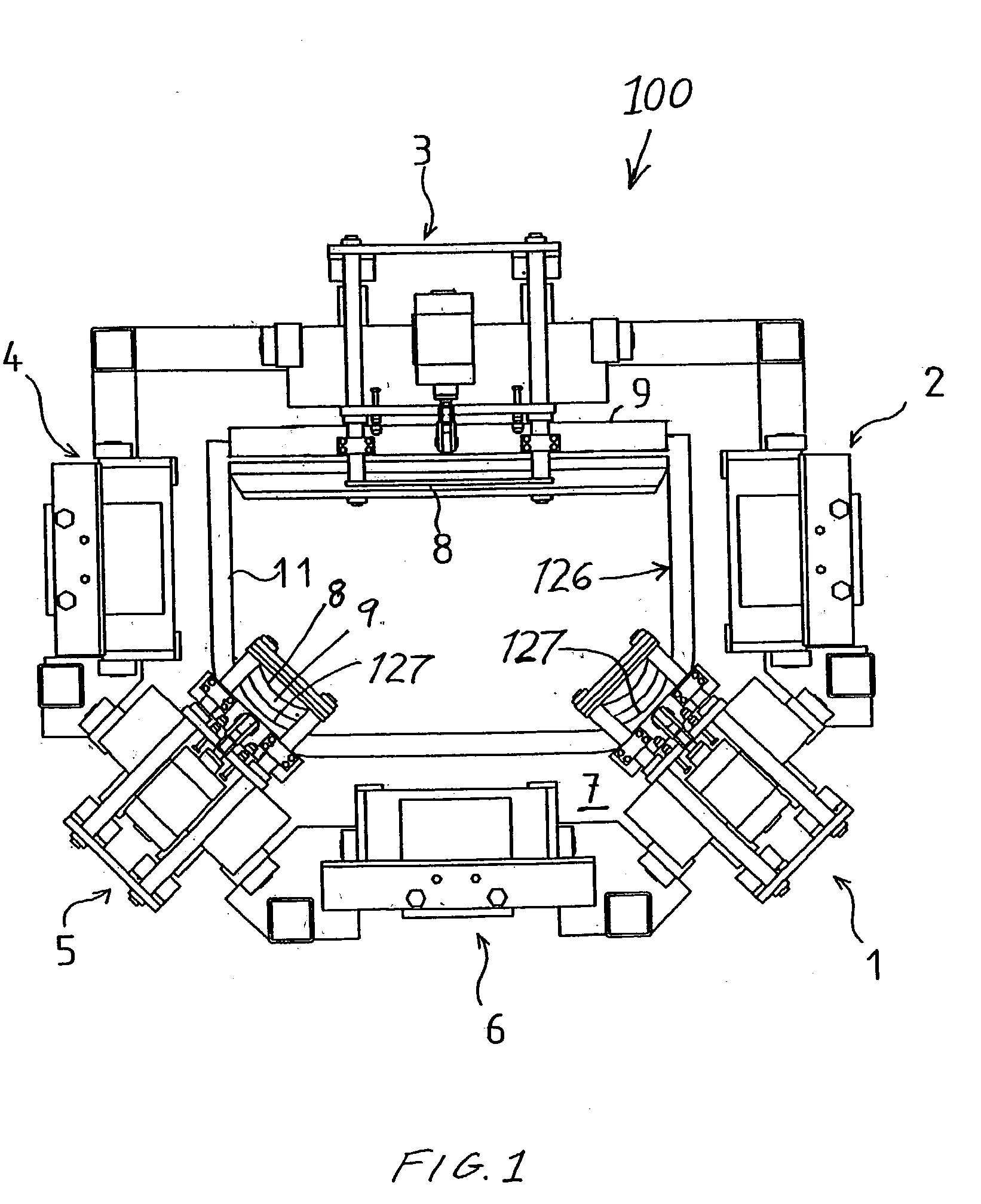
[0038] As generally schematically shown in FIG. 1, an apparatus 100 is provided for bending or folding an edge rim of a self-supporting thin-walled molded component. Herein, the term "self-supporting" means that the finished molded component generally maintains its molded shape and supports itself if it is secured at suitable locations, while still allowing for some flexibility and the like, and the term "thin-walled" means that the finished molded component has area dimensions that are much larger than (e.g. at least 10 or even at least 20 or 50 times) the thickness dimension thereof, as is typical of molded interior trim components for motor vehicles in this field. The apparatus 100 comprises six rim bending units 1, 2, 3, 4, 5, and 6 successively arranged around the perimeter of the outline or contour of the molded component. The bending units 1 to 6 are mounted and movably arranged in a machine frame 7. The apparatus further includes a mold 11 that carries and supports an unfini...


PUM

PropertyMeasurementUnit
temperatureaaaaaaaaaa
thicknessaaaaaaaaaa

Abstract

An apparatus includes several bending units for forming a singly-bent or doubly-folded edge rim around the perimeter of a molded component, e.g. a laminated contoured interior trim component for a motor vehicle. Each bending unit includes an electrically heatable cutting or impressing tool, and a bending tool. A workpiece holder clamps the component into a forming mold. The heated impressing tool melts and presses one or two grooves forming weakened zones and corresponding bending lines in the edge rim of the component. The bending tool then presses and bends the edge rim flange back along the bending line. Optionally, the bending tool additionally bends the free edge flange portion down along the second bending line to form the doubly-folded rim. The portions of the rim folded against each other are melt-bonded together and then cooled to permanently fix the bonded and folded configuration of the rim.

Description

PRIORITY CLAIM[0001] This application is based on and claims the priority under 35 U.S.C. .sctn.119 of Czechoslovakian Patent Application PV 2002-2129, filed on Jun. 18, 2002, the entire disclosure of which is incorporated herein by reference.[0002] The invention relates to a method and an apparatus for forming the free edge rim of a self-supporting, thin-walled molded component, such as a laminated and molded interior trim component for a motor vehicle. The edge rim is formed by bending, folding, and / or beading an edge rim flange of a raw or unfinished blank for the molded component.BACKGROUND INFORMATION[0003] Methods and apparatuses of the general type pertinent to the present invention are commonly known in a variety of different forms and embodiments. For example, the German Utility Model Publication DE 94 07 177 U1 discloses an apparatus that uses an electrical current and high frequency for achieving a heating effect, by means of which a binder or adhesive is activated for ad...

Claims


Application Information

Patent Timeline
Patent Type & Authority Applications(United States)
IPC IPC(8): B29C35/16B29C53/06B60R13/02
CPCB29C35/16B29C53/066B29C2035/1616Y10T428/13B29L2009/00B29L2031/3005B60R13/02B29C2035/1658
Inventor SPENGLER, ERNST MAXIMILIAN
Owner R S TECHN
Why Eureka
Try Eureka