Modulator, demodulator, and transmission system for use in OFDM transmission

a technology of modulator and demodulator, which is applied in the direction of digital transmission, orthogonal multiplex, electrical apparatus, etc., can solve the problems of inability to correctly demodulate ofdm symbols in this period, difficulty in obtaining synchronizing information directly from time-domain waveform, and inability to reproduce transmitted data

Inactive Publication Date: 2004-01-15
REDWOOD TECHNOLOGIES LLC
View PDF14 Cites 82 Cited by
  • Summary
  • Abstract
  • Description
  • Claims
  • Application Information

AI Technical Summary

Problems solved by technology

When a frequency error occurs in the OFDM signal on the transmitting and receiving ends, or when a timing error occurs and one symbol section cannot accurately be captured, the subcarriers suffer phase rotation and then the transmitted data cannot be reproduced.
That is to say, since the OFDM signal So presents a waveform like random noise, it is difficult to obtain the synchronizing information directly from the time-domain waveform.
In this case, the synchronizing symbols for several frames must be detected before establishing synchronization, and the OFDM symbols in this period cannot be correctly demodulated.
However, the synchronization errors between the transmitter and receiver easily occur due to variations in the transmission environment and the like, which cause clock error, frequency error, and time window error.
Hence, since the subcarriers of OFDM symbols demodulated when the errors are occurring have phase rotation errors, the transmitted data are erroneously reproduced.
Further, when the synchronizing symbols cannot be continuously detected at given intervals, stable synchronization cannot be established, and then it is very difficult to correctly demodulate the OFDM symbols transmitted in a burst manner.
However, when the subcarriers are differentially modulated, the amount of phase error correction can also be obtained by obtaining the absolute phase error.

Method used


Image

  • Modulator, demodulator, and transmission system for use in OFDM transmission
  • Modulator, demodulator, and transmission system for use in OFDM transmission
  • Modulator, demodulator, and transmission system for use in OFDM transmission

Examples


second example

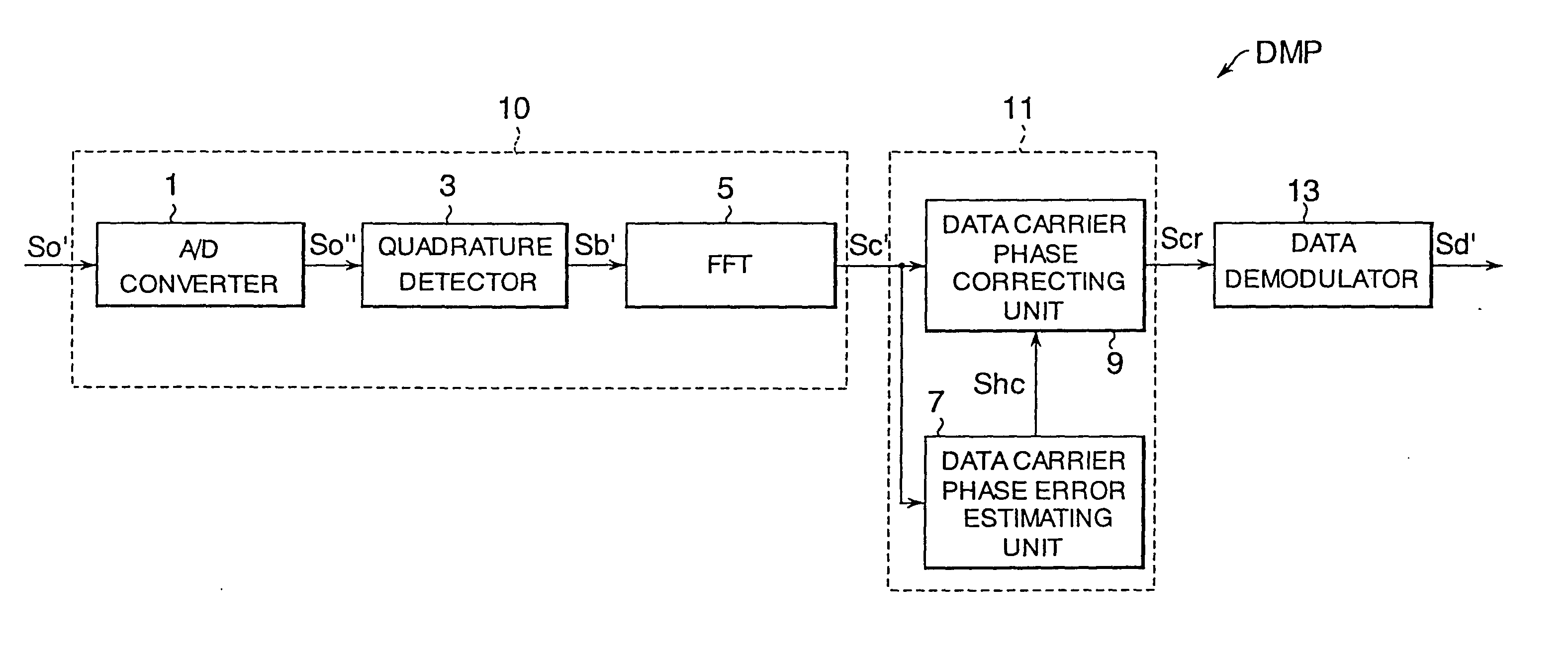
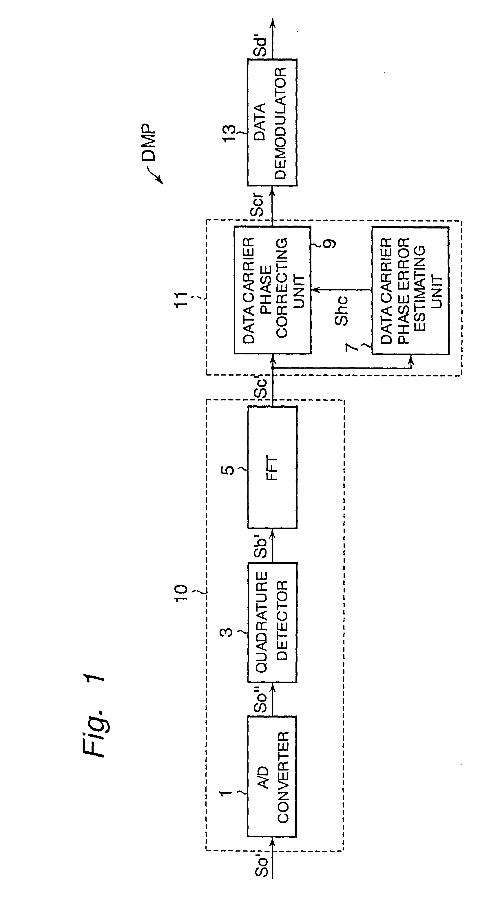
[0129] Referring to FIG. 6, the phase correcting unit 11 of a second example of the invention will be described. Unlike the phase correcting unit 11A of the first example, the phase correcting unit 11B in this example is especially suitable for the demodulation of an OFDM signal in which the subcarriers SC are subjected to differential modulation, such as the OFDM signal obtained in the OFDM modulator of the second embodiment described previously. When the data carriers DC are subjected to differential modulation between subcarriers adjacent in the frequency direction, the constant phase rotation due to frequency error is cancelled in differential demodulation, but the phase error due to timing error is added to the phase difference between adjacent carriers and then the differential demodulation cannot be achieved correctly.

[0130] FIG. 7 shows an OFDM signal subjected to differential modulation. The character k denotes Nos. of subcarriers SC. On the transmitting end, transmitted da...

third example

[0144] Referring to FIG. 8, the phase correcting unit 11 according to a third example of the present invention will be described. Similar to the phase correcting unit 11B of the second example, the phase correcting unit 11C of this example is especially suitable for the demodulation of an OFDM signal in which the subcarriers SC are modulated by means of differential modulation between subcarriers adjacent in the frequency direction. The phase correcting unit 11C has an inter-carrier phase difference calculating unit 6 between the data carrier phase correcting unit 9 and the fast Fourier transform unit 5 in the phase correcting unit 11B of the second example, and has the data demodulator 13 in place of the differential demodulator 15. Since the structure and operation of the data carrier phase error estimating unit 7B have already been explained, only the inter-carrier phase difference calculating unit 6 will be described.

[0145] The inter-carrier phase difference calculating unit 6 c...

first embodiment

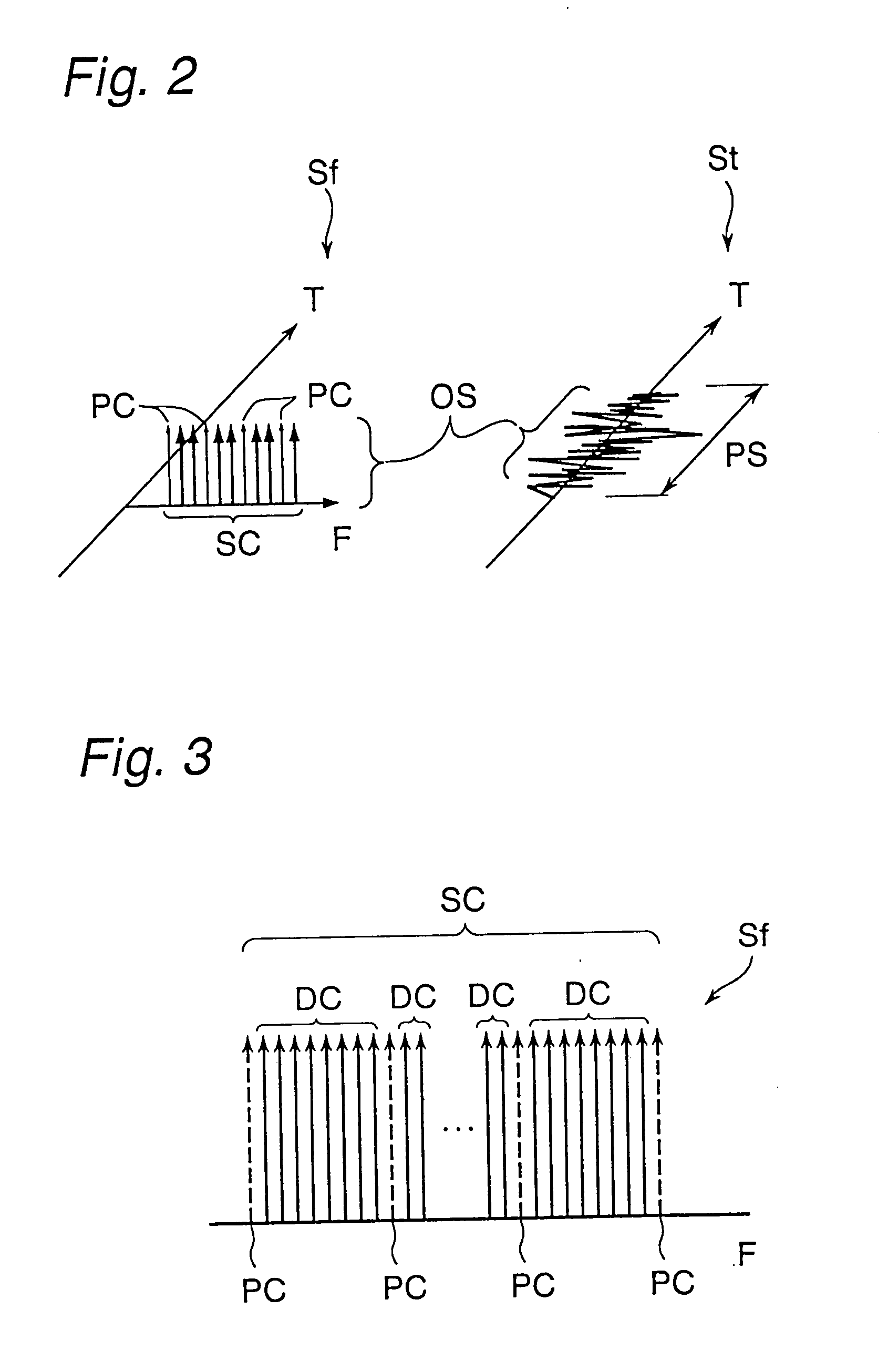
[0148] As stated above, the OFDM demodulators DMP of the present invention can accurately perform demodulation even when the synchronizing symbols RS are not inserted in frames like the OFDM signal shown in FIG. 13 due to the phase correction performed on the basis of the pilot carriers PC in known phase that are inserted in the OFDM symbols.


PUM


Abstract

An input of an OFDM signal containing known pilot carriers among given subcarriers is separated into subcarriers through Fourier transform in a fast Fourier transform unit. A data carrier phase error estimating unit obtains an amount of phase correction of each subcarrier on the basis of the pilot carriers in the separated subcarriers. A data carrier phase correcting unit corrects the phase of the separated subcarrier signal on the basis of the amount of phase correction. Thus, the phase errors of the subcarriers can be corrected and the OFDM symbols can be demodulated even if a frequency error and a timing error are occurring between the transmitter and receiver.

Description

[0001] This application is a divisional of Ser. No. 09 / 317,961, filed May 25, 1999.[0002] 1. Field of the Invention[0003] The present invention relates to a modulator and a demodulator used in Orthogonal Frequency Division Multiplex (hereinafter referred to as OFDM) transmission, and more particularly to a phase correcting technique.[0004] 2. Description of the Background Art[0005] Recently, a transmission system using the OFDM technique is attracting attention in digital audio broadcasting for mobile devices and terrestrial digital television broadcasting. The OFDM technique is a kind of multi-carrier modulation system, in which data to be transmitted (transmitted data) is assigned to a large number of subcarriers so arranged that adjacent subcarriers are orthogonal to each other and converted into a digital modulated signal in the time domain by inverse Fourier transform to generate an OFDM signal. In the OFDM transmission, the OFDM signal generated by applying the above-described...

Claims


Application Information

Patent Timeline
Patent Type & Authority Applications(United States)
IPC IPC(8): H04L27/26
CPCH04L27/2679H04L27/2657
Inventor SHIRAKATA, NAGANORIHARADA, YASUOHAYASHINO, HIROSHITANAKA, KOICHIRONAKAHARA, HIDEKI
Owner REDWOOD TECHNOLOGIES LLC
Why Eureka
Try Eureka