
Discriminating method for recording medium and recording apparatus

a recording medium and discrimination method technology, applied in the direction of image enhancement, digital output to print units, instruments, etc., can solve the problems of not being able to distinguish plain sheets from coated sheets, user may not obtain the quality of recorded images as desired in some cases, and difficulties, so as to improve discrimination accuracy, improve the quality of recording images, and improve the effect of discrimination

Inactive Publication Date: 2004-01-15
CANON KK
View PDF4 Cites 17 Cited by
  • Summary
  • Abstract
  • Description
  • Claims
  • Application Information

AI Technical Summary

Benefits of technology

[0029] In accordance with the present invention, it is possible to produce the following effects:
[0030] The characteristics needed for discriminating the kind of recording medium are acquired from the image information on any small area on the surface of a target-recording medium, and the kind of recording medium is discriminated on the basis of the result of such acquisition. Thus, as compared with the conventional method for discriminating recording medium by the utilization of reflection type optical sensor, it becomes possible to discriminate the kind of recording medium in higher precision. Particularly, the precision of discrimination can be enhanced for a plain sheet, a coated sheet for ink jet use, and an OHP film in particular. As a result, it is made possible to provide the environment under which various kinds of recording conditions can be selected and set optimally without forcing the user to carry out any complicated operation.
[0031] Also, the structure is arranged to use an image sensor, which makes it possible to confine the measuring location to one point when generating the image information of the surface of recording medium. As a result, it becomes unnecessary to move the recording medium or the sensor. Any mechanical structure for the movement thereof no longer needed as a matter of course.

Problems solved by technology

Then, however, if the user should wrongly set the suitable recording mode for the kind of the recording medium to be used, the user may fail in obtaining the quality of recorded image as desired in some cases.
However, in the conventional technology that has been described above, problems are encountered as given below.
As described above, it is not easy to discriminate the plain sheet from the coated sheet for ink jet use only in accordance with the values of regularly reflected light.
Therefore, this presents a large problem for the recording apparatus of ink jet method, because there is a need for different recording condition, such as the amount of ink discharge, the number of passes, which is the scanning frequency of the recording head for recording image of one-line portion, and some others, under which the recording apparatus of ink jet method should operate.
Also, for the recording apparatus of electrophotographic method, other than the recording apparatus of ink jet method, there is a fear that if the user should set the coated sheet for ink jet use, which is wrongly taken as the plain sheet, in a cassette for retaining recording the recording medium, the coated sheet may be wound around the fixing roller.
Nevertheless, as shown in FIG. 34, the distribution areas of the plain sheet and coated sheet for ink jet use may be overlapped even by the application of the intensities of the diffused reflection lights for both of them, which makes it difficult to make the discrimination of the kind exactly.
1. Conventionally, the coating of calcium carbonate to the surface of a recording medium has not been preferred due to the problem that the fixing roller of a copying machine is worn off by the coating thereof.
The coating of calcium carbonate is effective in enhancing the whiteness of a recording medium, while it becomes more difficult to discriminate the plain sheet having higher whiteness with the coating of calcium carbonate from the coated sheet for ink jet use.
However, for the recording medium the kind of which are different, there exist some of them that indicate the same value when the comparison is taken, although the absolute values of the respective intensities of the regularly reflected light and diffused reflection light are different, which makes it difficult to make the discrimination of the kind of recording medium.
Also, when the absolute values of the intensities of the regularly reflected light and diffused reflection light are used for parameters to discriminate the kind of the recording medium, not the comparative values between them, there is a need for highly precise correction, which should unavoidably lead to the increased costs of a recording apparatus.
This makes it difficult to make the discrimination of the kind of recording medium always in good precision.
Also, it takes a time for the sensor that measures the reflected light or it takes a time for effectuating measurements at plural locations along with the movement of a recording medium.
As a result, the user is forced to endure a waiting time.
As a result, it becomes unnecessary to move the recording medium or the sensor.

Method used


Image

  • Discriminating method for recording medium and recording apparatus
  • Discriminating method for recording medium and recording apparatus
  • Discriminating method for recording medium and recording apparatus

Examples


first embodiment

[0066] (First Embodiment)

[0067] Hereunder, with reference to the accompanying drawings, the detailed description will be made of a first embodiment that materializes the present invention.

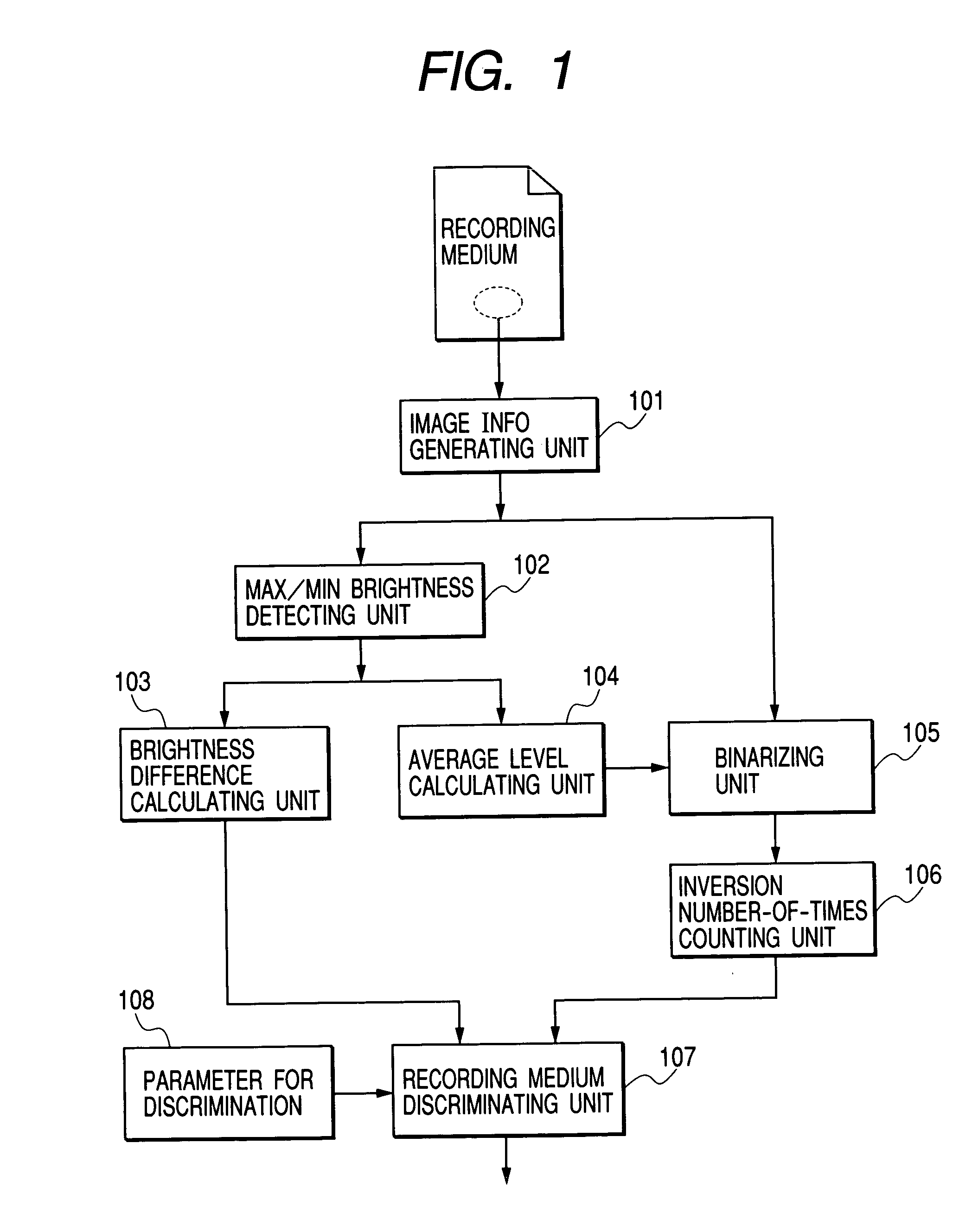
[0068] FIG. 1 is a functional block diagram that shows a method for discriminating recording medium in accordance with the first embodiment.

[0069] In FIG. 1, a reference numeral 101 designates an image information-generating unit that generates image information from any (or arbitrary) fine area on the surface of a recording medium. The image, which is generated in this image information-generating unit, is formed by plural pixels having the brightness value larger than the binary. Here, it is assumed that such image is the aggregation of pixels having 8-bit brightness information. At this time, it is not needed to give heed to whether each pixel has color information of RGB or not. For the present embodiment, the image information is generated by the component of diffused reflection light, and eac...

second embodiment

[0139] (Second Embodiment)

[0140] Hereunder, with reference to the accompanying drawings, the description will be made of a second embodiment of the present invention.

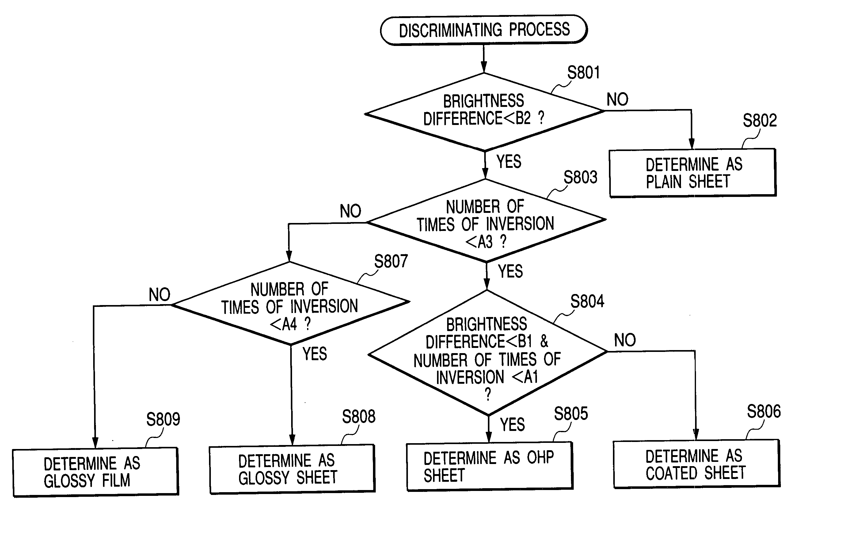
[0141] The recording medium-discriminating method that materializes the present embodiment is characterized in that whereas the first embodiment uses the brightness difference and the number of inversions after the execution of the binarizing process for discriminating the kind of recording medium, this embodiment is designed to discriminate the kind of recording medium by use of arithmetic mean value and the amount of run-length codes. Therefore, the description will be made centering on such event.

[0142] FIG. 12 is a functional block diagram that shows the recording medium-discriminating method in accordance with the second embodiment.

[0143] A reference numeral 1201 designates an image information-generating unit that generates image information form any small area on the surface of a recording medium. As in the case ...

third embodiment

[0170] (Third Embodiment)

[0171] Hereunder, with reference to the accompanying drawings, the description will be made of a third embodiment of the present invention.

[0172] The recording medium-discriminating method that materializes the present embodiment is characterized in that the kind of recording medium are discriminated by use of the rightness difference and the isolated number of pixels. Therefore, the description will be made centering on such event. The process flow and the flow of discrimination are almost the same as those of the first embodiment, and the description thereof will be omitted.

[0173] FIG. 18 is a functional block diagram that shows the recording medium-discriminating method in accordance with the third embodiment.

[0174] A reference numeral 1801 designates an image information-generating unit that generates image information form any small area on the surface of a recording medium. The process in which the image information is generated from the diffused refle...


PUM


Abstract

A method for discriminating the kind of a recording medium comprises generating the image information composed by plural pixels corresponding to a specific area on the surface of a recording medium as image information indicating the surface condition of the recording medium, obtaining a first parameter regarding the surface roughness of the recording medium, from the image information, obtaining a second parameter regarding the surface configuration of the recording medium, and discriminating the kind of the recording medium in accordance with the first parameter and the second parameter. With the structure thus arranged, the method obtains the characteristics of the surface of the recording medium from an image on the surface of the recording medium, and discriminates the kind of recording medium reliably in high precision.

Description

[0001] 1. Field of the Invention[0002] The present invention relates to a method for discriminating recording medium that discriminates the kind thereof, and a recording apparatus, which is provided with a function to discriminate the kind of recording medium. The invention also relates to a program that executes the discrimination of the kind of recording medium, and a storage that stores such program as well. More particularly, the invention relates to the technology of discriminating the kind of recording medium in accordance with image information obtainable form the surface of recording medium.[0003] 2. Related Background Art[0004] Conventionally, as the output apparatus of a printing system that expels recording medium having images recorded thereon by the formation of color images with the adhesion of color toners or ink on the recording surface of such recording medium, there have been made available those of various methods, such as electro-photographic method, wire-dot met...

Claims


Application Information

Patent Timeline
IPC IPC(8): B65H7/14G01B11/24G01B11/30B41J2/01G01N21/84G06T7/40
CPCG01B11/30G06T2207/10152G06T2207/10008G06T7/401G06T7/41
Inventor TSUJIMOTO, TAKUYA
Owner CANON KK
Learn More