
Shape memory polymer or alloy ophthalmic lens mold and methods of forming ophthalmic products

Inactive Publication Date: 2004-01-22
JOHNSON & JOHNSON VISION CARE INC
View PDF9 Cites 67 Cited by
  • Summary
  • Abstract
  • Description
  • Claims
  • Application Information

AI Technical Summary

Benefits of technology

[0011] The mold of this invention comprising an SMP or SMA can be used to make a lens and then re-shaped and re-used to form another lens, thereby reducing the amount of mold material consumed in a lens manufacturing facility. Additionally in alternative embodiments, the molds formed by the methods described below can be used to produce more varied contact lenses and even customized contact lenses at a lower cost than if metal inserts had to be fabricated to make each mold member. Additionally, by using the mold of this invention in manufacturing ophthalmic products, a mechanical demold step, used in the prior art to remove an ophthalmic product molded within the mold, may be eliminated and replaced with the step of heating the mold comprising a SMP or SMA above its Tg to cause the mold to deform, at which time the ophthalmic product can be removed from the mold without the mechanical demold step.

Problems solved by technology

Production and maintenance costs for the mold inventory are high.
The injection molding step just described to form the ophthalmic lens mold members limits the types of materials that can be used to form the lens molds.
This method is disadvantageous in that it is unsuitable for the production of certain ophthalmic lenses, such as soft contact lenses because soft contact lens materials are thermoset that cannot be deformed with heat.
Additionally, this method is disadvantageous in that molding the lens material using a heated die requires that the lens blanks' optical axis be perfectly aligned with that of the die, which adds a great degree of difficulty to production of the lens.
Once the deformation is locked in, the polymer network cannot return to a relaxed state due to thermal barriers.
Further cooling will likely only increase the cooling time.
(Actually if the surface roughness of the adjustment means without any layer is low enough, although this would complicate the fabrication of the adjustment means, the layer of the agile mold would be optional even if the optical forming surface of the mold is the surface pressed against the adjustment means.)

Method used


Image

  • Shape memory polymer or alloy ophthalmic lens mold and methods of forming ophthalmic products
  • Shape memory polymer or alloy ophthalmic lens mold and methods of forming ophthalmic products
  • Shape memory polymer or alloy ophthalmic lens mold and methods of forming ophthalmic products

Examples


example 2

[0113] A polymeric reaction mixture was formulated by mixing vinyl neodecanoate (7%), divinyl benzene (1%), and styrene (60%) in random order to form a colorless solution. Polystyrene granules (30%) were then added to the resulting solution. The resulting mixture was then allowed to sit at room temperature with occasional stirring until all the polystyrene granules were dissolved to give a clear, viscous solution. Benzoyl peroxide (2%) was then added to the resulting solution (all composition % are by weight). The resulting mixture was ultrasonicated at room temperature for 15 minutes to yield a clear solution. The resulting solution was kept cold in a refrigerator before use. To prepare the shape memory polymer (SMP), the reaction mixture formulated above was injected by syringe into a mold fabricated with two 14" by 14" glass plates separated by Viton spacer. The two sheets of glass were held together by clamps around the edges. The Viton spacer also acts as sealant in the mold. T...

example 3

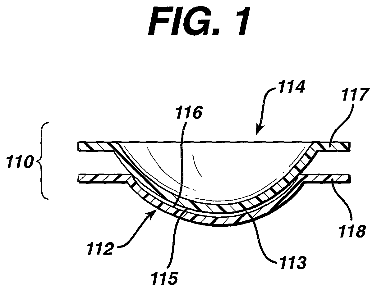
[0116] A sheet of polynorbornene SMP having a wide thickness variation of between 0.65 mm and 0.85 mm was cut into discs that were accommodated in a holding device of the type illustrated in the drawings. The SMP disc, disposed in the holding device, was placed in an alignment jig of the type depicted in the drawings and disposed between a base curve element and a core element of the type shown in the drawings.

[0117] The thus formed assembly was disposed on a hot plate and a 25 lb weight was placed atop the core element. The SMP sample was heated to a temperature slightly in excess of its glass transition temperature and then the pressure was applied. It is emphasized that this temperature was in excess of the curing temperature of the SMP polynorborene

[0118] The SMP disc, pressed between the core and base curve elements, was formed into the shape of the base curve element. Thereupon, the 25 lb weight and the hot plate were removed and the apparatus was cooled to ambient temperature...

example 4

[0122] Another example, in accordance with that described in Example 3, was conducted in which four female SMP contact lens mold halves were formed of the same sheet of polynorbornene used in Example 1. However, the four molds were fabricated using four different base curve elements. Thus each mold was formed from a different press assembly.

[0123] The measured results reported for this example were identical to the results reported in Example 3 with the exception that the surface roughness of the metal inserts was also reported, using the same instruments used in Example 3. However, two additional comparisons were included in this example. The first additional comparison was a measurement of the surface roughness of the SMP sheet from which the SMP molds were formed. This measurement was made in accordance with the procedure utilized in the determination of the surface roughness of the SMP molds and metal inserts. The second additional comparison was another surface roughness measur...


PUM

PropertyMeasurementUnit
Surface roughnessaaaaaaaaaa
Lengthaaaaaaaaaa
Lengthaaaaaaaaaa

Abstract

A shape memory polymer contact lens mold is formed from a sheet of a shape memory polymer in a press, an agile tool or by an agile tool formed by an inert gas at a temperature at or above the glass transition temperature which is thereupon cooled to below the glass transition temperature and removed therefrom.

Description

[0001] This is a continuation-in-part of U.S. Ser. No. 09 / 649,635 filed Aug. 28, 2000 entitled, "Deformable Molds And Methods For Their Use In The Manufacture Of Ophthalmic Lenses", and this application claims priority from provisional application Serial No. 60 / 263,986, filed Jan. 24, 2001, both applications are incorporated herein by reference.1. FIELD OF THE INVENTION[0002] The present invention relates to the manufacture of ophthalmic products. In particular, the invention provides molds for forming ophthalmic products, and methods for forming the molds and ophthalmic products using the molds.2. BACKGROUND OF THE INVENTION[0003] The use of ophthalmic lenses, including spectacle lenses, contact lenses, intraocular lenses, and the like for the correction of ametropia is well known. Production of the lenses requires the use of molds that impart the desired corrective characteristics onto the lens surfaces. Typically, a large inventory of molds is required corresponding to each spher...

Claims


Application Information

Patent Timeline
IPC IPC(8): B29C33/38B29C45/00B29C61/06B29D11/00B29D11/02C08F212/08
CPCB29C33/38B29C45/0001B29C61/06B29C61/0608B29D11/00125Y10S425/808B29D11/023B29K2101/10B29K2995/0073C08F212/08B29D11/00432B29D11/00009B29D11/00557B29D11/00019
Inventor HOFMANN, GREGORY J.FOLEY, KENNETH W.ROONEY, THOMAS R.HOOD, PATRICK J.
Owner JOHNSON & JOHNSON VISION CARE INC
Learn More