
Anti-spalling combination on an impact tool with an improved holding system

a technology of anti-spalming and impact tools, which is applied in the direction of manufacturing tools, grain treatment, light and heating equipment, etc., can solve the problems of not offering a solution to the problem of spalling after substantial use, and achieve the effects of reducing the number of impact tools, preventing injuries, and limiting or eliminating spalling

Inactive Publication Date: 2004-01-29
HARD HAT TECH
View PDF10 Cites 8 Cited by
  • Summary
  • Abstract
  • Description
  • Claims
  • Application Information

AI Technical Summary

Benefits of technology

[0002] The inventors have designed a tool to be struck, or a striking tool, (collectively referred to as an "impact tool"), or alternatively, a cap, that will not suffer metal spall and the attendant dangers from noise and from spalling and flying or cutting metal slivers. The noise production characteristics of impact of an impacting tool (such as a ram or hammer) striking a tool to be struck, or of the tool to be struck can be modified. By further modifying the working end of the tool, impact effectiveness can be maintained.
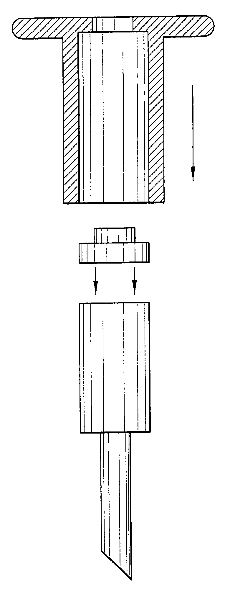
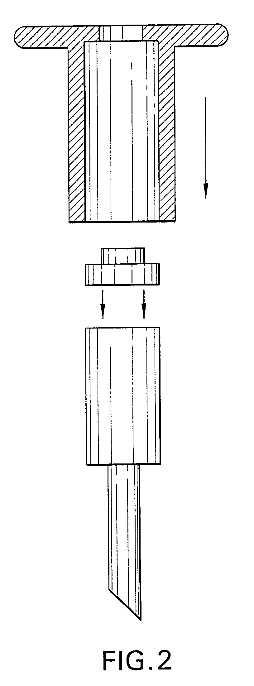
[0004] The key benefit of the invention relates to protection of the tool and more importantly, the worker, from attendant noise, fatigue, spalling and its consequences. For a striking tool, a disk would be positioned above and on the striking end of a diameter approximately equal to the diameter of the striking end or the diameter of the end of a striking tool, such as a hammer, whichever diameter is less. The disk would be made of a material which would not spall or shatter and would still effectively perform the designated task. The disk would be preferably secured by a cap with an aperture to accommodate the disk made of a less expensive material with a lower modulus and good impact resistance. The disk protects the end of the tool from spalling. For an application involving an impacting tool with an interchangeable working end, a disk would be positioned in between the impacting end and the striking end of the interchangeable working end.
[0005] Replacement of such disk or other shape would be contemplated. Alternatively the material could be more fully and more permanently integrated into the striking end of a striking tool or the impacting end of an impacting tool or both. Selection of polymers and polymeric composites can be made to include lubricity characteristics. A system for automated impacters or automated repeat impacters includes polymers, polymeric composites and / or metals inserted between impacting end of the impacter and the striking end of a striking tool. This arrangement will reduce vibrations, noise, and improve ergonomics.

Problems solved by technology

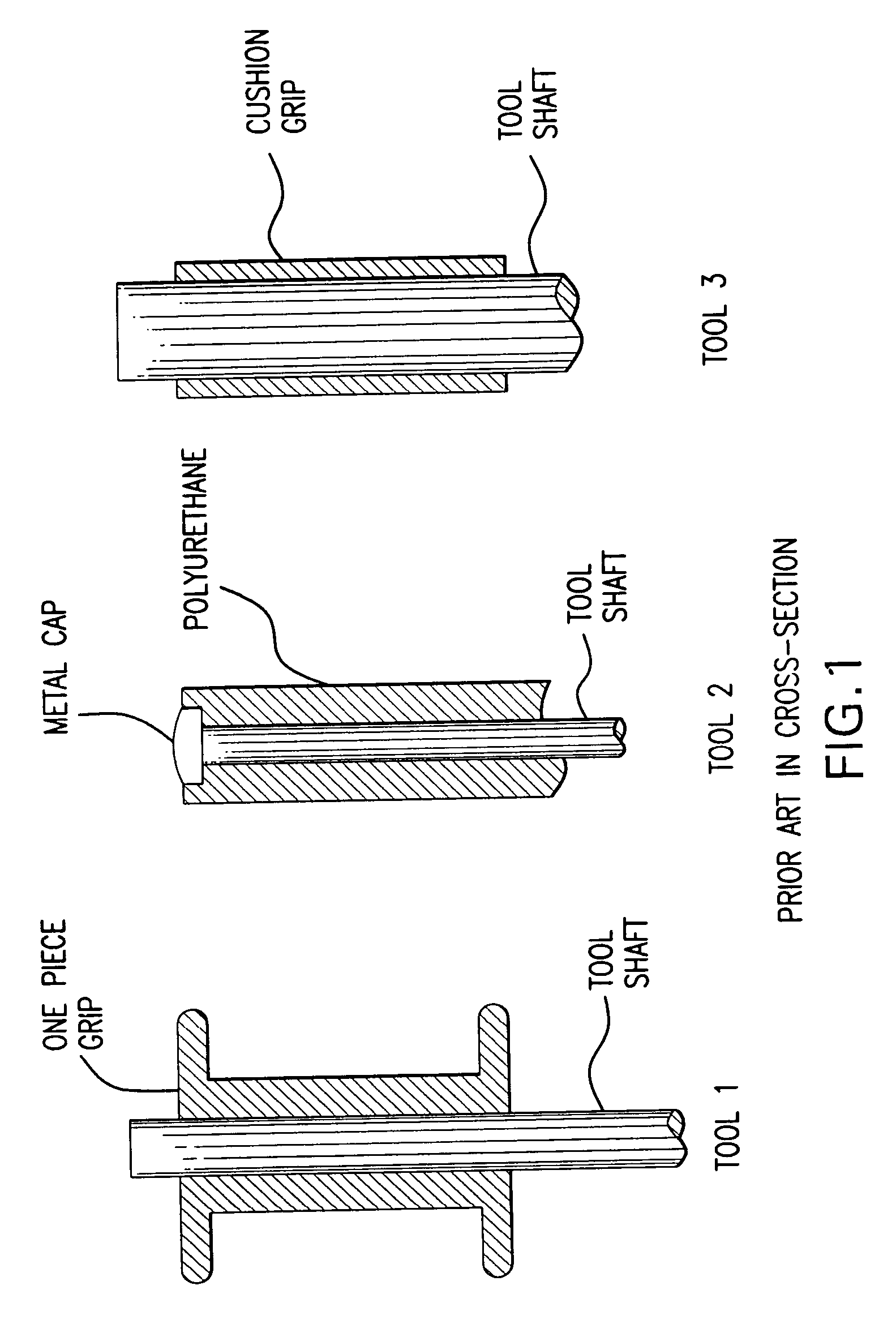
Tool 2 of FIG. 1 has high transmission of force and some hand-holding advantages, but furnishes no solution to the problem of spalling after substantial use.

Method used


Image

  • Anti-spalling combination on an impact tool with an improved holding system
  • Anti-spalling combination on an impact tool with an improved holding system
  • Anti-spalling combination on an impact tool with an improved holding system

Examples


Embodiment Construction

[0013] The preferred mode of invention is applicable to any tool used for impact applications. Such tool is generally referred to as an impact tool, and includes tools that are impacted or struck, or tools that impact and strike, such as a hammer, or an automated repeating impact tool such as a jackhammer.

[0014] As related in the summary above, the basic design of several preferred modes is useful for understanding the scope of the invention. The basic and a first preferred mode which illustrates the basic principles of the invention is on a tool to be struck such as a chisel (wood or cold). A wedge is another suitable mode of employment of the invention. The chisel would have a striking end cut square to the shaft. The striking end would be opposite the working end. The chisel is illustrative of the first preferred mode involving tools to be struck. Other examples are wedges and spikes.

[0015] For a striking tool, a disk would be positioned above and on the striking end. There are t...


PUM

PropertyMeasurementUnit
thicknessaaaaaaaaaa
thicknessaaaaaaaaaa
modulusaaaaaaaaaa

Abstract

The invention is a tool to be struck, or a striking tool, (collectively referred to as an "impact tool"), or alternatively, a cap, that will not suffer metal spall and the attendant dangers of spalling and flying or cutting metal slivers. The preferred mode is on a chisel (wood or cold) or repeated impact tool. The chisel would have a striking end cut square to the shaft. The striking end would be opposite the working end. Other tools such as impact wrenches, jackhammers, wedges, spikes, hammers, mallets or other tools being struck or striking forcibly benefit from the invention by use of a disk insert of polymeric material to alter ergonomic and noise characteristic.

Description

CONTINUATION DATA[0001] For purposes of the United States, this is a continuation in part of PCT / US02 / 23448 and entry into the national stage of PCT / US02 / 23448 filed in the United States as Receiving Office, which PCT Application PCT / US02 / 23448 in turn is a continuation in part of provisional applications filed on Jul. 23, 2001 Nos. 60 / 307,198, and 60 / 356,804 filed on Feb. 13, 2002, both filed in the United States.SUMMARY OF INVENTION[0002] The inventors have designed a tool to be struck, or a striking tool, (collectively referred to as an "impact tool"), or alternatively, a cap, that will not suffer metal spall and the attendant dangers from noise and from spalling and flying or cutting metal slivers. The noise production characteristics of impact of an impacting tool (such as a ram or hammer) striking a tool to be struck, or of the tool to be struck can be modified. By further modifying the working end of the tool, impact effectiveness can be maintained.[0003] The preferred mode i...

Claims


Application Information

Patent Timeline
Patent Type & Authority Applications(United States)
IPC IPC(8): B25D1/16B25D3/00B25G1/01
CPCB25D1/16B25G1/01B25D3/00Y10T83/04
Inventor MCCARTY, H. DOWNMAN IISCHUMM, BROOKE IIIPOPPER, PETER
Owner HARD HAT TECH
Learn More