High-peak-power laser device and application to the generation of light in the extreme ultraviolet

a laser device and laser technology, applied in the direction of lasers, optical devices for lasers, instruments, etc., can solve the problems of complex and expensive lasers obtained by a very sophisticated and expensive technology, and use of complex and expensive optical amplifiers

Inactive Publication Date: 2004-02-05
COMMISSARIAT A LENERGIE ATOMIQUE ET AUX ENERGIES ALTERNATIVES
View PDF8 Cites 24 Cited by
  • Summary
  • Abstract
  • Description
  • Claims
  • Application Information

AI Technical Summary

Benefits of technology

[0038] The term "spatial superposition" is taken to mean the superposition of a plurality of laser beams substantially onto the same spot of the target, substantially at the same time. The term "substantially at the same time" means that the temporal offsets between the various elementary pulses respectively supplied by the solid-state lasers of the laser device are small compared with the repetition period of these lasers. This superposition makes it possible to increase the energy per pulse and the peak powers.
[0039] As will be seen below, flexibility of use can be obtained with superposition of the laser beams on virtually the same spot and at virtually the same time. This flexibility of use makes it possible to optimize emission from the plasma created.
[0042] This makes it possible to increase the peak power and to have considerable freedom to modify the spatial distribution of the light pulse which results from the addition of the elementary light pulses emitted by the lasers.

Problems solved by technology

The result thereof is a complex and expensive laser.
on the other hand, photolithography applications which require pulses which are short and, if possible, at a high rate, obtained by a very sophisticated and expensive technology using in particular two optical amplification stages.
In addition, it uses complex and expensive optical amplifiers.

Method used


Image

  • High-peak-power laser device and application to the generation of light in the extreme ultraviolet
  • High-peak-power laser device and application to the generation of light in the extreme ultraviolet
  • High-peak-power laser device and application to the generation of light in the extreme ultraviolet

Examples


Embodiment Construction

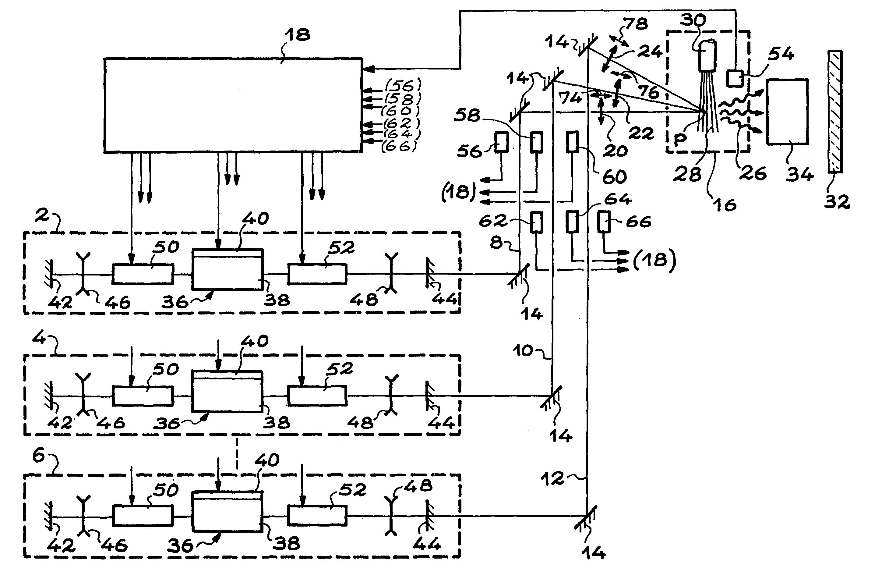
[0079] The device according to the invention, which is schematically shown in FIG. 4, comprises more than three pulsed lasers, for example eight, but only three of them are shown in this FIG. 4 and have the references 2, 4 and 6 respectively.

[0080] The light beams 8, 10 and 12 (more exactly, the light pulses) which are respectively supplied by these pulsed lasers 2, 4 and 6, are directed, via a set of mirrors 14, substantially onto the same point P of a target 16 and substantially at the same time onto this point P.

[0081] Means 18 for controlling the lasers have also been shown, making it possible to obtain the light pulses.

[0082] FIG. 4 also shows focusing means 20, 22 and 24 which are provided to focus the light beams 8, 10 and 12 respectively on the point P of the target 16.

[0083] In the example in question, the lasers and the target are chosen in order to supply, by interaction of the light beams with this target, EUV radiation 26. To do this, the target comprises for example a ...


PUM

PropertyMeasurementUnit
wavelengthsaaaaaaaaaa
energyaaaaaaaaaa
diameteraaaaaaaaaa

Abstract

This device comprises at least three pulsed lasers (2, 4, 6), in order to supply light pulses, and means (14) for directing these pulses substantially onto the same spot of a target (16) and substantially at the same time onto this spot. The lasers are pumped by diodes (40) operating continuously.

Description

[0001] The present invention relates to a laser device of high peak power and of average power and of high repetition rate, while at the same time being of minimum cost and complexity.[0002] The invention is applicable in particular to the generation of light in the extreme ultraviolet region.[0003] Radiation belonging to this region, which is also called "EUV radiation", has wavelengths ranging from 8 nanometres to 25 nanometres.[0004] The EUV radiation which can be obtained by making light pulses, generated with the device which is the subject of the invention, interact with a suitable target has numerous applications, especially in materials science, microscopy and most particularly in microlithography, in order to fabricate integrated circuits with a very high degree of integration. For this last application, it is particularly advantageous to have a high repetition rate, which is very difficult to obtain for high-peak-power lasers.[0005] The invention is applicable to any field...

Claims


Application Information

Patent Timeline
Patent Type & Authority Applications(United States)
IPC IPC(8): G03F7/20H01S3/00H01S3/23H01L21/027
CPCG03F7/70025H01S3/2383H01S3/005H01S3/23
Inventor WEULERSSE, JEAN-MARLE FLANCHEC, VINCENTGILBERT, MICHEL
Owner COMMISSARIAT A LENERGIE ATOMIQUE ET AUX ENERGIES ALTERNATIVES
Why Eureka
Try Eureka