Sealing structure of fuel cell and manufacturing method of same

a fuel cell and sealing structure technology, applied in the manufacture of final products, cell components, electrochemical generators, etc., can solve the problems of reducing positioning accuracy, reducing positioning accuracy, so as to prevent the positioning accuracy in stacking cells from being reduced and reducing positioning accuracy

Active Publication Date: 2004-02-05
TOYOTA JIDOSHA KK
View PDF4 Cites 11 Cited by
  • Summary
  • Abstract
  • Description
  • Claims
  • Application Information

AI Technical Summary

Benefits of technology

0010] In the stack structure of a fuel cell, the protruding portion is provided, and the tip portion thereof contacts the reference portion of the assembly jig. Accordingly, the adhesive agent does not come out from the tip portion of the protruding portion. Also, it is possible to prevent the positioning accuracy in stacking the cells from being reduced. The reduction of the positioning accuracy is due to adhesion of the spreading adhesive agent to the reference portion of the assembly jig.
0011] A stack structure of a fuel cell according to a further aspect of the invention includes a plurality of cells each of which is formed of separators and an MEA, and a protruding portion which is formed on an end portion of each of the separators so as to protrude in the direction perpendicular to the cell stacked direction, and which is formed so as not to overlap with the protruding portion of the adjacent separator in a cell stacked direction. Thus, the protruding portions of the separators adjacent to each other (e.g., the separator on an anode side and the separator on a cathode side, when the separators adjacent to each other are the separator on the anode side and the separator on the cathode side) are displaced from each other in the cell stacked direction. Accordingly, even if the protruding portions are deformed, the protruding portions do not contact with each other, which can prevent a short-circuit from occurring. The occurrence of the short-circuit is due to deformation of the separators caused by making the separators contact the reference portion of the assembly jig.

Problems solved by technology

However, there exist the following problems regarding the conventional method for assembling the cell stacked body.
First, the adhesive agent comes out of the gap between the separators to the notched portion when forming a cell, and the adhesive agent, which has come out, adheres to the reference portion of the assembly jig when forming a cell or a stack, which may reduce the positioning accuracy.
Secondly, the separator is deformed due to a pressing load when the separator is pressed to the reference portion of the assembly jig, and the anode side separator and the cathode side separator, which are adjacent to each other with the electrolyte membrane therebetween, come into contact with each other, which may cause a short-circuit.
The reduction of the positioning accuracy is due to adhesion of a spreading adhesive agent to a reference portion of an assembly jig.
The occurrence of the short-circuit is due to deformation of the separator caused by making the separator contact the reference portion of the assembly jig.
The reduction of the positioning accuracy is due to adhesion of the spreading adhesive agent to the reference portion of the assembly jig.
The occurrence of the short-circuit is due to deformation of the separators caused by making the separators contact the reference portion of the assembly jig.

Method used


Image

  • Sealing structure of fuel cell and manufacturing method of same
  • Sealing structure of fuel cell and manufacturing method of same
  • Sealing structure of fuel cell and manufacturing method of same

Examples


Embodiment Construction

the PREFERRED EMBODIMENTS

[0025] Hereafter, a stack structure of a fuel cell according to the invention will be described with reference to FIGS. 1 to 12. The fuel cell according to the invention is a solid polymer electrolyte membrane fuel cell 100. The fuel cell 100 is mounted, for example, on a fuel-cell vehicle. However, the fuel cell 100 may be employed in products other than an automobile.

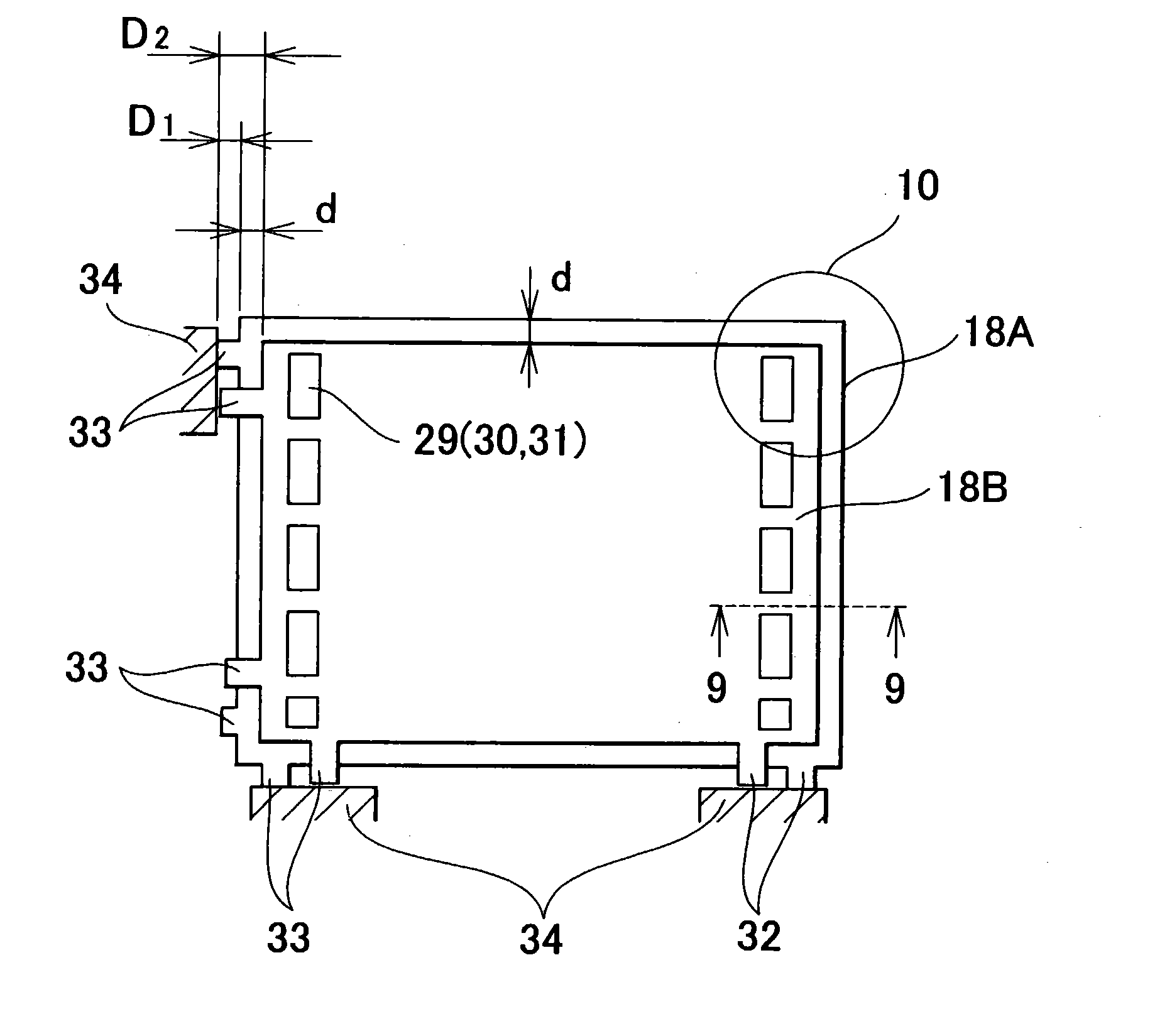
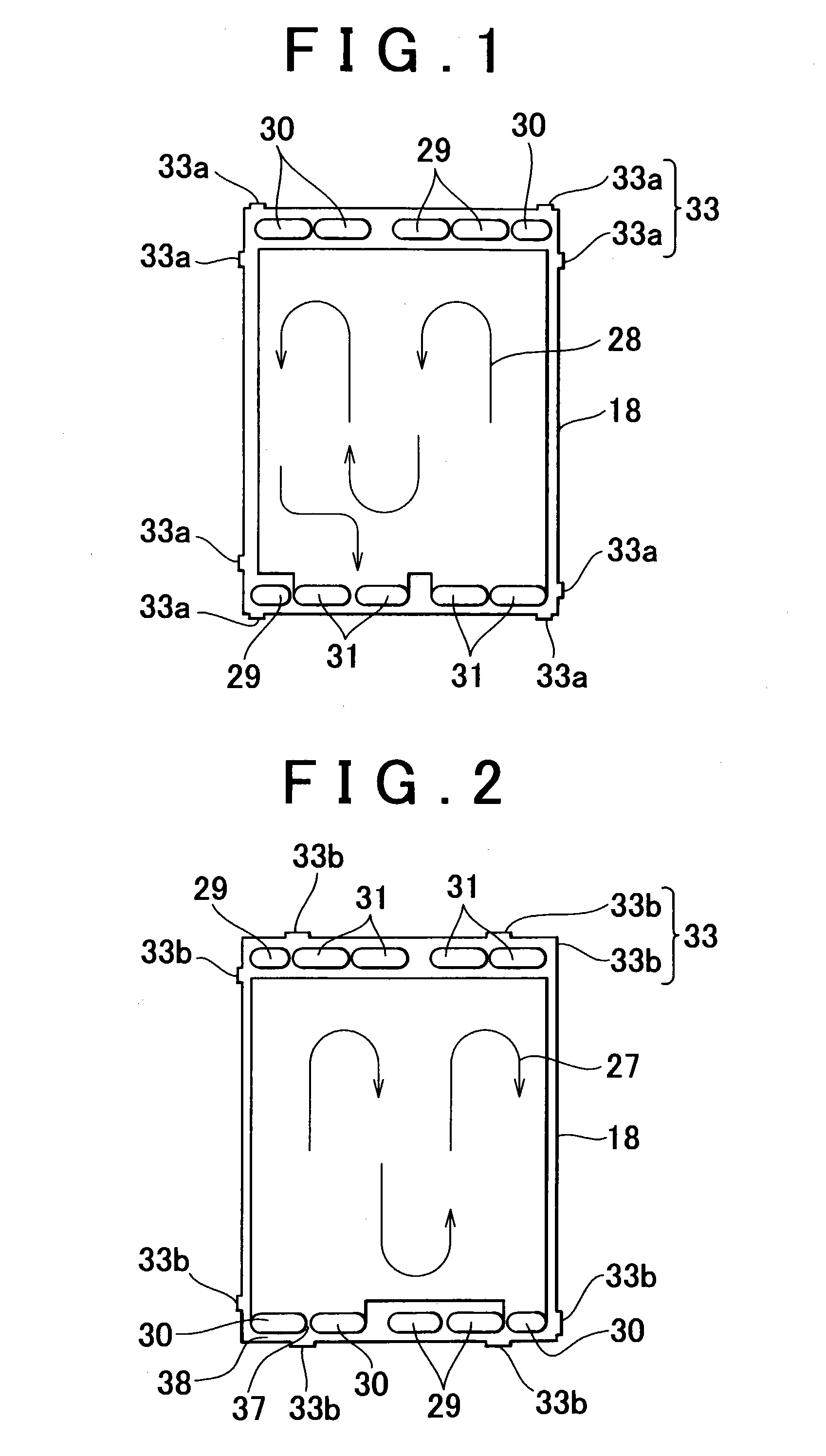
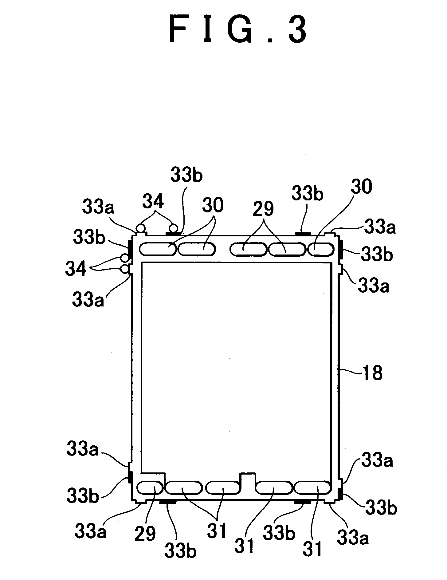
[0026] As shown in FIGS. 11, 12, the solid polymer electrolyte membrane fuel cell 100 includes a plurality of Membrane-Electrode Assemblies (i.e., MEAs) and a plurality of separators 18. Each of the MEAs includes an electrolyte membrane 11 formed of an ion-exchange membrane, an electrode (i.e., an anode, a fuel electrode) 14 having a catalyst layer 12 which is provided on one surface of the electrolyte membrane 11, and an electrode (i.e., cathode, an air electrode) 17 having a catalyst layer 15 which is provided on the other surface of the electrolyte membrane 11. A diffusion layers 13 is prov...


PUM

PropertyMeasurementUnit
heightaaaaaaaaaa
heightaaaaaaaaaa
heightaaaaaaaaaa

Abstract

A stack structure of a fuel cell according to an aspect of the invention includes a plurality of separators of the fuel cell, and a protruding portion which has a tip portion that contacts a reference portion of an assembly jig during assembly of the fuel cell. Since the tip portion of the protruding portion contacts the reference portion of the assembly jig, an adhesive agent does not come out from the tip portion of the protruding portion. Therefore, it is possible to prevent positioning accuracy in stacking cells from being reduced. The reduction of the positioning accuracy is due to adhesion of the spreading adhesive agent to the reference portion of the assembly jig. In addition, it is possible to prevent a short-circuit from occurring. The occurrence of the short-circuit is due to deformation of the separator caused by making the separator contact the reference portion of the assembly jig.

Description

INCORPORATION BY REFERENCE[0001] The disclosure of Japanese Patent Applications No. 2002-223319 filed on Jul. 31, 2002 and No. 2003-136702 filed on May 15, 2003 including the specification, drawings and abstract is incorporated herein by reference in its entirety.[0002] 1. Field of Invention[0003] The invention relates to a stack structure of a fuel cell, and a manufacturing method of same.[0004] 2. Description of Related Art[0005] A solid polymer electrolyte membrane fuel cell includes a plurality of Membrane-Electrode Assemblies (i.e., MEAs) and a plurality of separators. Each of the MEAs includes an electrolyte membrane formed of an ion-exchange membrane, an electrode (i.e., an anode, a fuel electrode) formed of a catalyst layer which is provided on one surface of the electrolyte membrane, and an electrode (i.e., a cathode, an air electrode) formed of a catalyst layer which is provided on the other surface of the electrolyte membrane. A diffusion layer is provided between the MEA...

Claims


Application Information

Patent Timeline
Patent Type & Authority Applications(United States)
IPC IPC(8): H01M8/02H01M8/10H01M8/24
CPCH01M8/0247H01M8/0258Y02E60/50H01M8/241H01M8/2465H01M8/0271H01M8/2404Y02P70/50H01M8/2483H01M8/0267H01M8/0263
Inventor AKIYAMA, SHIROASAI, YASUYUKISUZUKI, TOSHIYUKINAKAJI, HIROYA
Owner TOYOTA JIDOSHA KK
Why Eureka
Try Eureka