Method and computer programme for operating an internal combustion engine and an internal combustion engine

a technology of internal combustion engine and computer program, which is applied in the direction of electric control, fuel injection control, mechanical equipment, etc., can solve the problems of increased tendency for knocking, uncontrolled precombustion, and engine service life, and achieve the effect of low price and lower power

Inactive Publication Date: 2004-02-12
WUERFEL GERNOT
View PDF15 Cites 7 Cited by
  • Summary
  • Abstract
  • Description
  • Claims
  • Application Information

AI Technical Summary

Benefits of technology

0024] It is, however, also possible that the ignition of the mixture takes place by means of a glow device. In this case, there is therefore no separation between injection and ignition. Instead, the combustion operation is initiated by the start of the injection. The flame core formation also takes place at a point similar as in a spark ignition at an electrode, namely, in the hot surroundings of the glow device because the glow device its

Problems solved by technology

Such a high compression ratio is, up to now, not possible because, especially at full load operation, this can lead to uncontrolled precombustions of the gasoline disposed in the combustion chamber for a higher geometric and effective compression ratio.
A further problem with respect to the service life of the engine is caused by a g

Method used


Image

  • Method and computer programme for operating an internal combustion engine and an internal combustion engine
  • Method and computer programme for operating an internal combustion engine and an internal combustion engine
  • Method and computer programme for operating an internal combustion engine and an internal combustion engine

Examples


Embodiment Construction

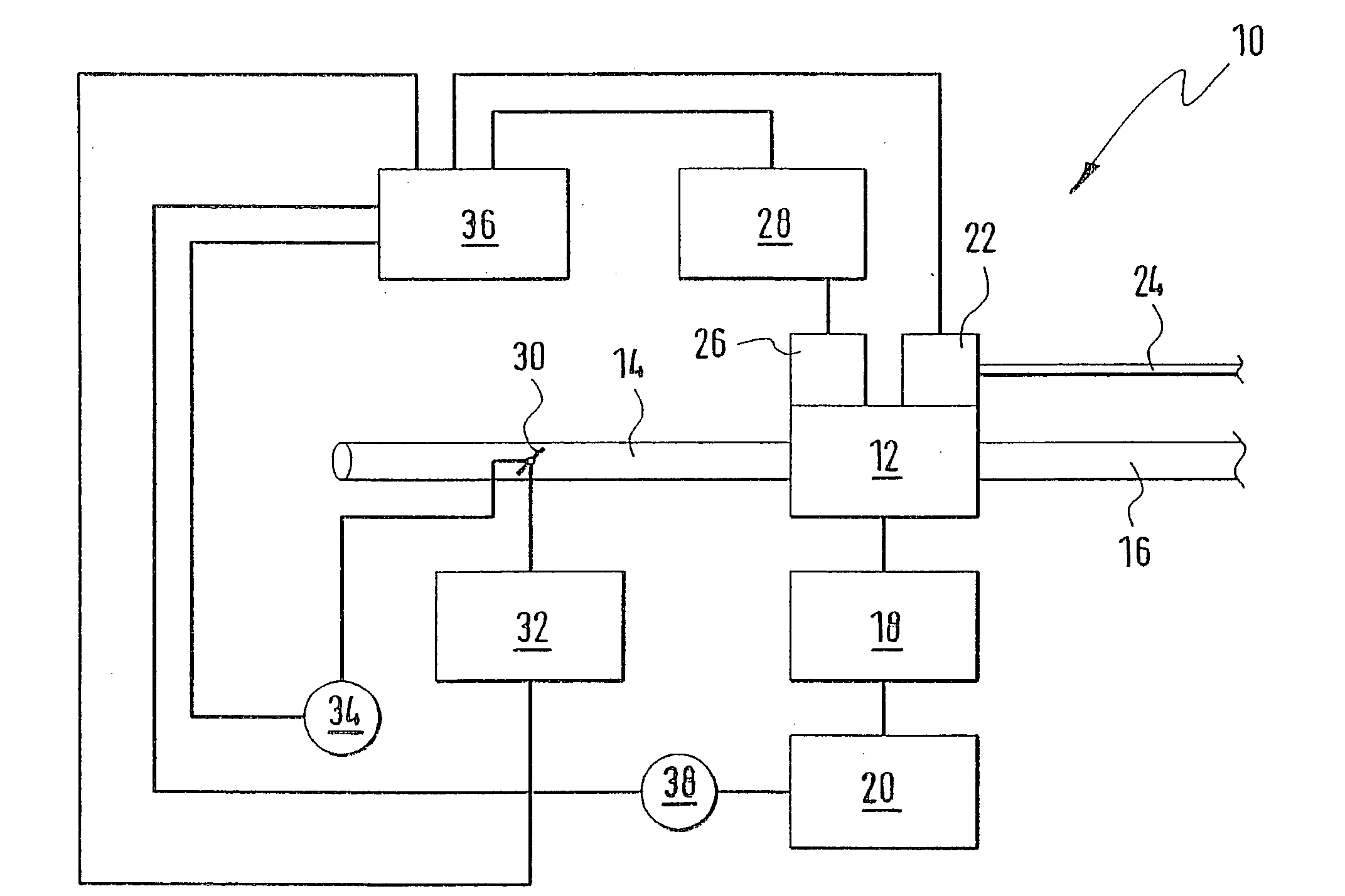
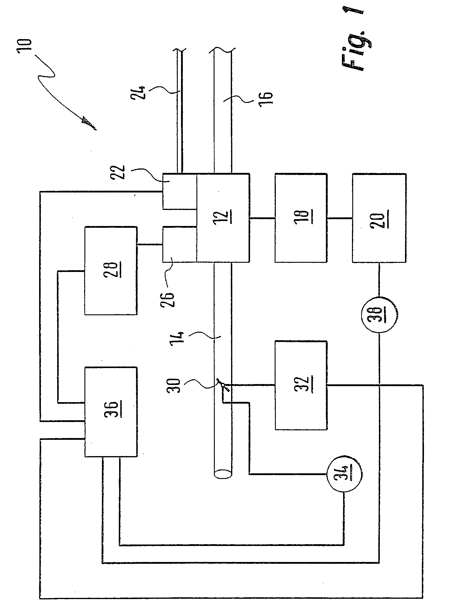
[0034] In FIG. 1, an internal combustion engine is identified by reference numeral 10. The engine includes a combustion chamber 12 to which air is supplied via an intake manifold 14. The exhaust gases are directed away from the combustion chamber 12 via an exhaust-gas pipe 16.

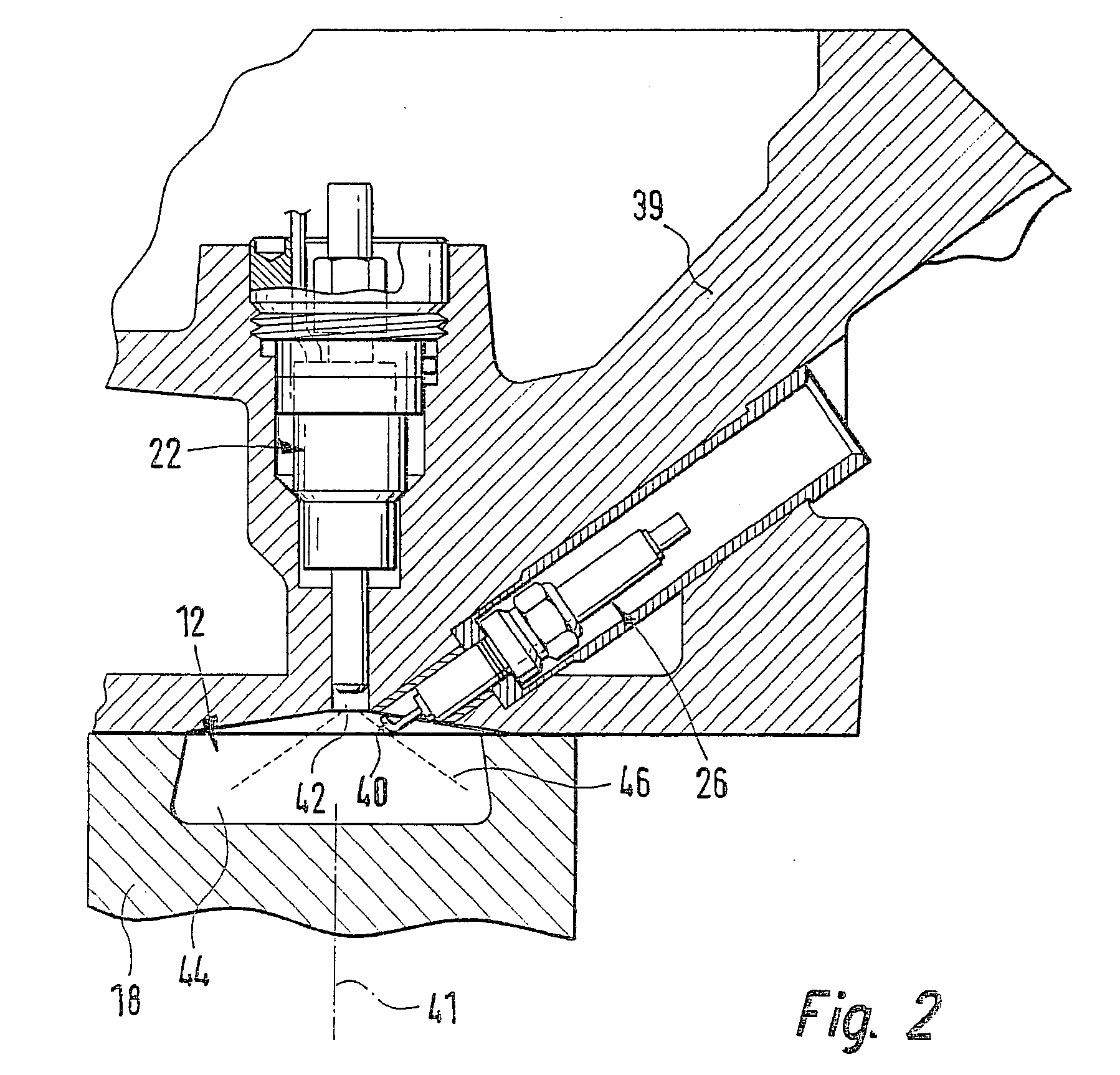
[0035] The combustion chamber 12 is delimited downwardly by a piston 18 which operates on a crankshaft 20. Gasoline is injected into the combustion chamber 12 via a high pressure injection valve 22 which is connected to a gasoline collection line 24. The gasoline collection line 24 is also known as a rail. The air / gasoline mixture disposed in the combustion chamber 12 is ignited by a spark plug 26 which is supplied by an ignition device 28.

[0036] A throttle flap 30 is present in the intake manifold 14 which is moved by an actuating motor 32. The angular position of the throttle flap 30 is detected by a position transducer 34 which transmits corresponding signals to a control apparatus 36. The control apparatus ...


PUM


Abstract

An internal combustion engine (10) is operated with a method wherein fuel is injected directly into a combustion chamber (12). The injection takes place at least from time to time so that, together with a corresponding supply of air into the combustion chamber (12), the air/gasoline mixture is present stratified in the combustion chamber (12). In order to reduce the gasoline consumption in the engine (10) via a higher compression ratio without the danger of knocking, it is suggested that the gasoline be injected exclusively and also at full load during the compression phase of the engine (12) by a multi-hole fuel injection device (22).

Description

STATE OF THE ART[0001] The present invention relates to a method for operating an internal combustion engine wherein gasoline is so injected directly into a combustion chamber at least from time to time and air is so supplied to the combustion chamber at least from time to time that the gasoline / air mixture in the combustion chamber of the engine is present stratified.[0002] Such a method is characterized generally as a method for gasoline-direct injection. In this method, the gasoline is charged with a very high pressure in a fuel collection line referred to as a rail. High pressure injection valves are connected to the fuel collection line and these valves inject the gasoline directly into the combustion chamber. The gasoline is so injected into the combustion chamber that a rather rich air / gasoline mixture is present in the direct vicinity of the ignition device which mixture can be ignited. The air / gasoline mixture is very lean in the remainder of the combustion chamber. In the ...

Claims


Application Information

Patent Timeline
IPC IPC(8): F02B37/00F02B1/08F02B17/00F02B23/10F02B75/12F02D23/02F02D41/02F02D41/04F02D41/30F02D43/00F02D45/00F02P5/15
CPCF02B1/08F02B17/00Y02T10/123F02B2075/125F02D41/3023F02B23/101Y02T10/12
Inventor WUERFEL, GERNOT
Owner WUERFEL GERNOT
Why Eureka
Try Eureka