Low weight high performance composite vessel and method of making same

a composite vessel, low weight technology, applied in the direction of vessel construction details, mechanical equipment, transportation and packaging, etc., can solve the problems of limiting affecting the performance of the tank, so as to achieve the effect of low weight, minimal wall thickness and high level of consolidation

Inactive Publication Date: 2004-02-12
KAISER COMPOSITEK
View PDF7 Cites 63 Cited by
  • Summary
  • Abstract
  • Description
  • Claims
  • Application Information

AI Technical Summary

Benefits of technology

0023] The tank or vessel in the present invention is characterized by the fact that the tank is essentially formed of a reinforced plastic composite material which is relatively light in weight and which, along with an outer shell, carries a substantial portion of any pressure induced loads. The liner also is effective to be relatively impermeable to gases contained under pressure.
0024] The tank of the invention can also be considered to be a two shell tank without any inner liner. The tank is comprised of an inner shell which, in addition to carrying load, also effectively functions as a mandrel for an outer shell to be formed, as hereinafter described, and together with the outer shell actually forms the pressure vessel

Problems solved by technology

However, the inner liner substantially increases the weight of the vessel, but provides little or no ability to receive any of the load on the vessel and thus, the liner weight may be regarded as parasitic.
Another problem encountered in the manufacture of the presently available storage tank or vessel is the fact that components, such as fittings, are frequently connected to the tank and it would be desirable to connect these components from the inside thereof.
However, most of the conventional commercially used processes for fabricating tanks do not allow for the formation of the tank in such manner that access to the interior can be obtained.
Moreover, they typically remain pressurized until the propellant has b

Method used


Image

  • Low weight high performance composite vessel and method of making same
  • Low weight high performance composite vessel and method of making same
  • Low weight high performance composite vessel and method of making same

Examples


Embodiment Construction

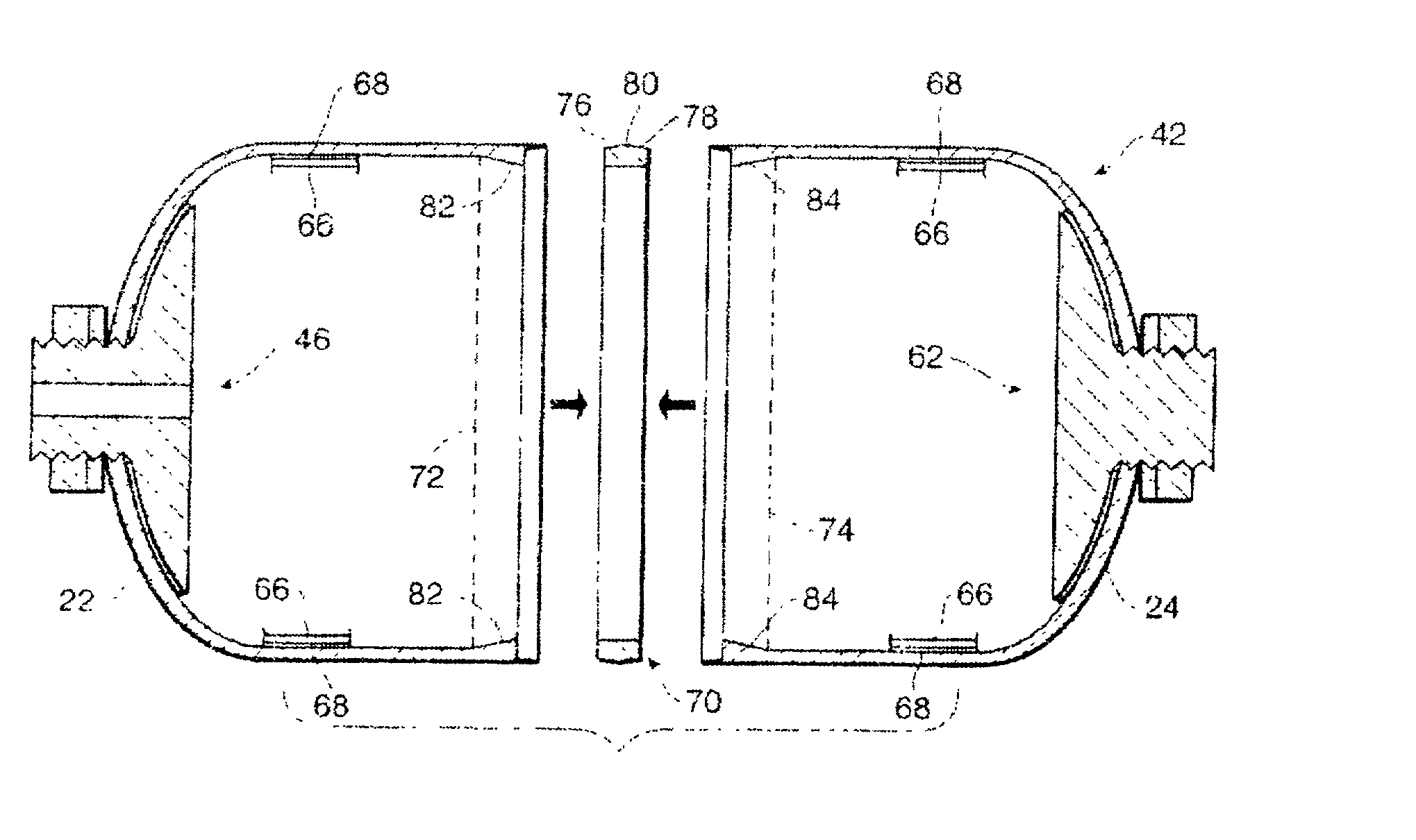
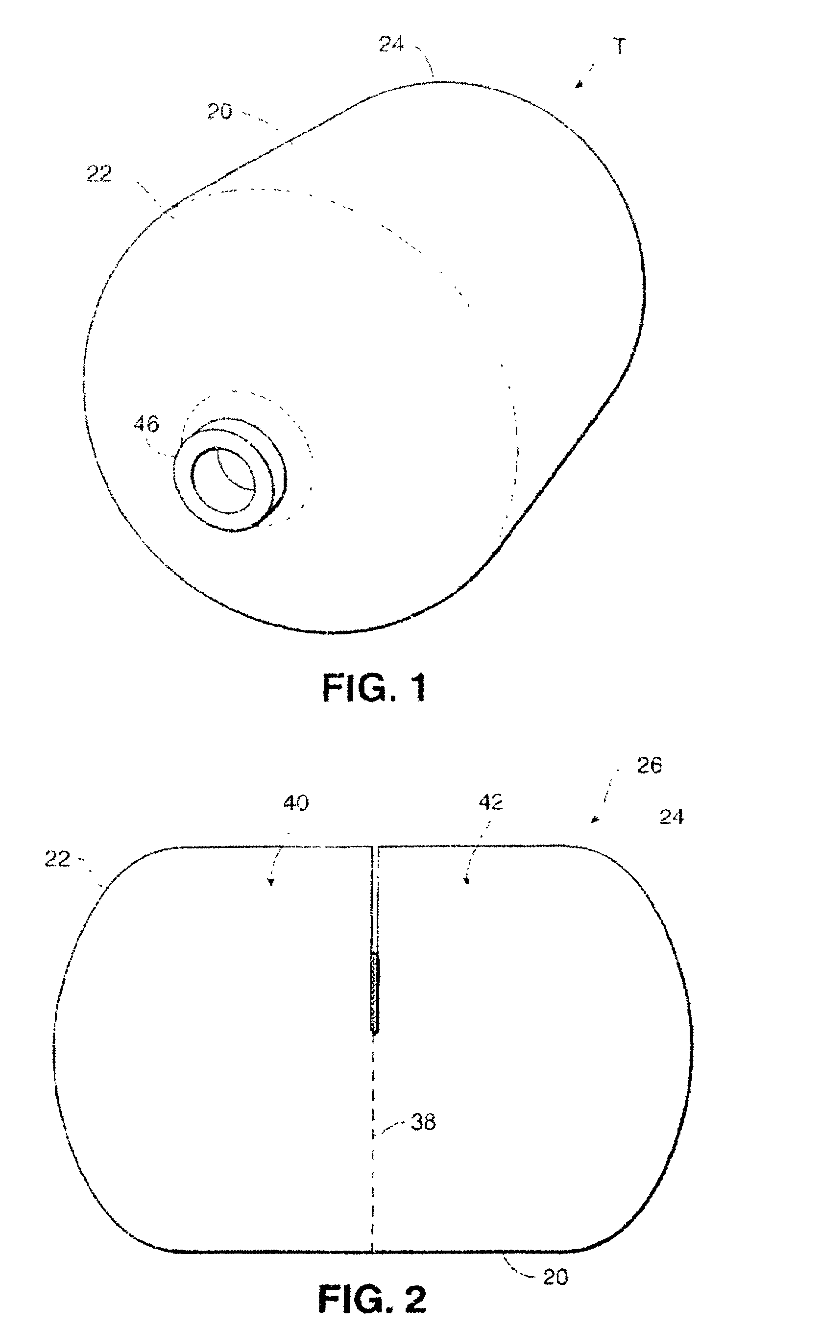
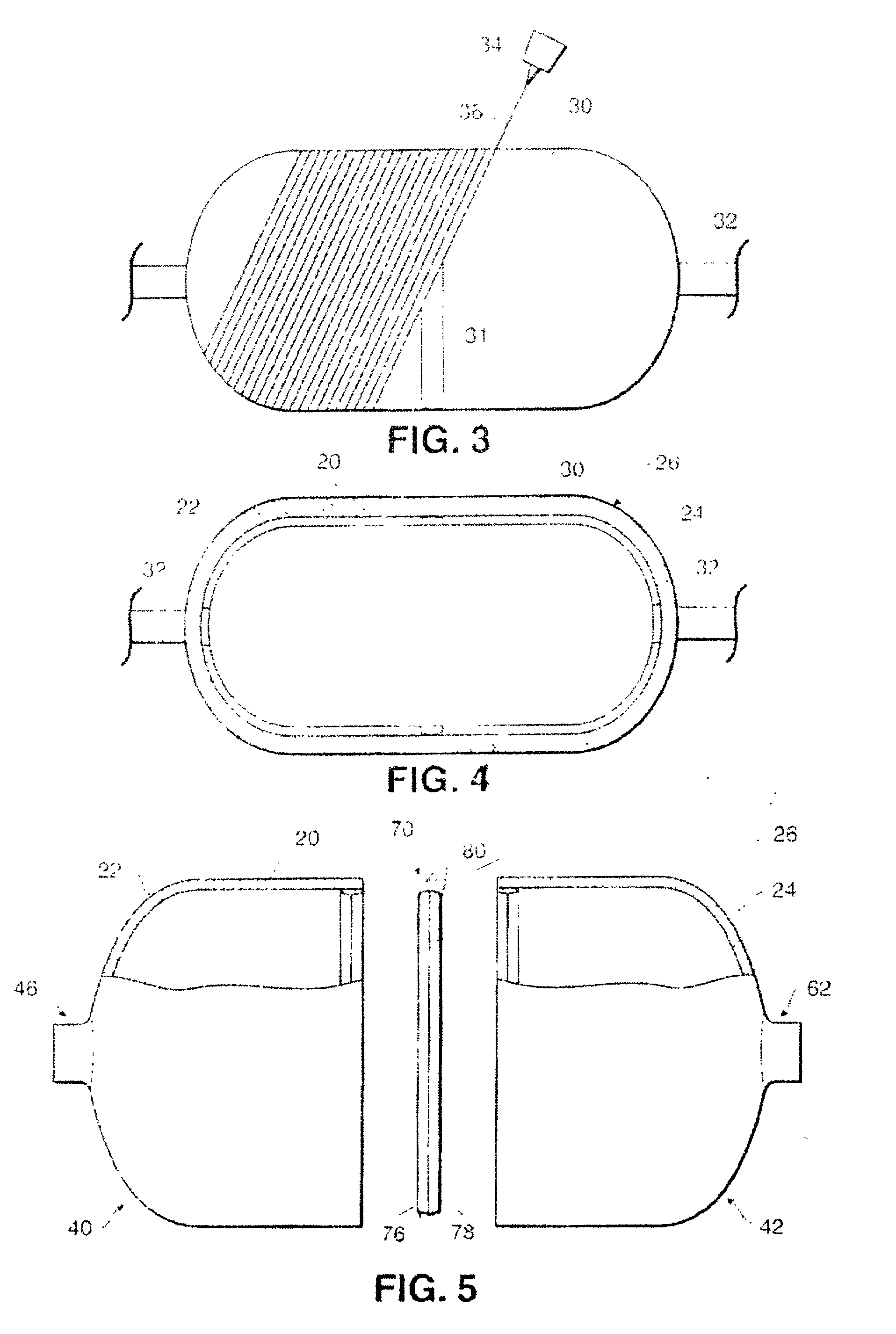
[0051] Referring now in more detail and by reference characters to the drawings, which illustrate practical embodiments of the present invention, T designates a storage vessel or tank constructed in accordance with the present invention. In this particular embodiment, as illustrated, the tank is elongate and has a cylindrically shaped side wall 20, as well as semi-ellipsoidal or similar shaped end-piece, or so-called "domes", 22 and 24 in the manner as best shown in FIGS. 1-3 of the drawings. It should be understood, however, that any shape of tank and any size of tank could be constructed in accordance with the method of the present invention.

[0052] The tank T does not include an inner liner, as aforesaid, but does include an inner shell and an outer shell, in a manner to be hereinafter described in more detail. An inner shell 26 forming part of the tank is also shown in FIGS. 2 and 3 of the drawings. The inner shell 26 may be formed in any of a variety of ways, although it is pref...


PUM

PropertyMeasurementUnit
Weightaaaaaaaaaa
Pressureaaaaaaaaaa
Altitudeaaaaaaaaaa

Abstract

A light weight high performance vessel, e.g., tank and method of making same which is produced primarily from reinforced plastic composite materials. The vessel can be used for the containment of liquids or pressurized gases. The tank is comprised of an inner shell which is split to remove a mandrel on which it is formed and to install components in the inner shell. The inner shell pieces are then secured together by means of a joinder ring. An outer shell is then formed around and completely encapsulates the inner shell. There is also no need for the employment of an inner liner although one can be used.

Description

[0001] 1. Field of the Invention[0002] This invention relates in general to certain new and useful improvements in lightweight pressure vessels and more particularly, to a lightweight pressure vessel which is formed primarily of composite materials, and a method of making same. An inner shell of the tank is formed and then separated into a plurality of sections and allowing for removal of a mandrel and installation of vessel components, and which sections are then secured together in a unique manner and provided with an outer load bearing shell, to thereby provide a lightweight high performance tank.[0003] 2. Brief Description of Related Art[0004] Many modern storage vessels, such as pressure vessels, are frequently formed with inner liners for leakproof containment of fluids and particularly gases under pressure. An outer load-bearing shell is frequently constructed of composite material so as to provide the load bearing capacity and durability needed for a pressure vessel.[0005] P...

Claims


Application Information

Patent Timeline
IPC IPC(8): F17C1/06
CPCF17C1/06F17C2270/025F17C2201/056F17C2203/0604F17C2203/0619F17C2203/0621F17C2203/066F17C2203/0665F17C2203/0668F17C2203/067F17C2205/0397F17C2209/2163F17C2209/22F17C2209/227F17C2221/033F17C2223/0123F17C2223/036F17C2260/012F17C2260/036F17C2270/0168F17C2270/0194F17C2201/0109
Inventor JONES, BRIAN H.
Owner KAISER COMPOSITEK
Why Eureka
Try Eureka