Seal cavity throat protectors

a throat protector and sealing cavity technology, applied in the direction of engine seals, non-positive displacement fluid engines, liquid fuel engine components, etc., can solve the problems of increased pressure difference, increased difficulty of penetration, and increased pressure of seals

Inactive Publication Date: 2004-02-12
PRINZ GMBH & CO KG
View PDF17 Cites 13 Cited by
  • Summary
  • Abstract
  • Description
  • Claims
  • Application Information

AI Technical Summary

Problems solved by technology

Such fluid may contain various contaminants which arise from erosion of the surfaces of the equipment and which may be abrasive.
The seals are also susceptible to damage by contaminants in the fluid.
In addition, labyrinth-type seals have previously been devised to increase the difficulty of penetration by contaminants into the seal cavity.
However, it has been found that such protectors tend to create too great a difference in pressure which in turn increases fluid flow into the seal cavity, as well as increasing wear on the shaft and components of the device.
While these patents disclosed the use of grooves and seal...

Method used


Image

  • Seal cavity throat protectors
  • Seal cavity throat protectors
  • Seal cavity throat protectors

Examples


Embodiment Construction

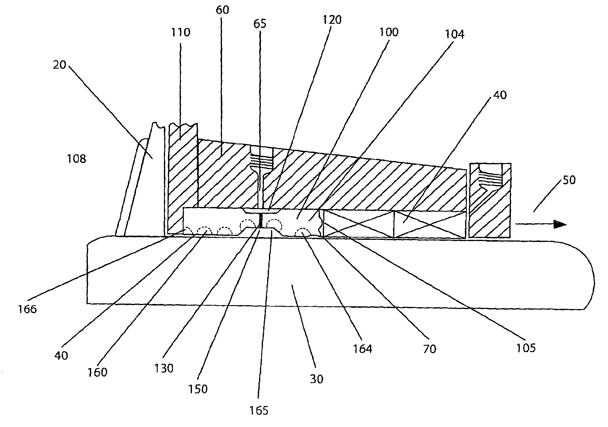
[0046] FIG. 1 depicts a typical environment for a seal cavity throat protector in the form of a bushing according to the present invention which is shown generally at 100. The environment includes an operative portion such as an impeller 20, which is connected to a shaft 30, the shaft 30 being connected to a prime mover such as a motor 40 (not shown). Seals 40 protect bearings which support the shaft which would be further along the shaft in the direction of arrow 50. Shaft 30 together with shaft housing 60 and seals 40 form a seal cavity shown generally at 70.

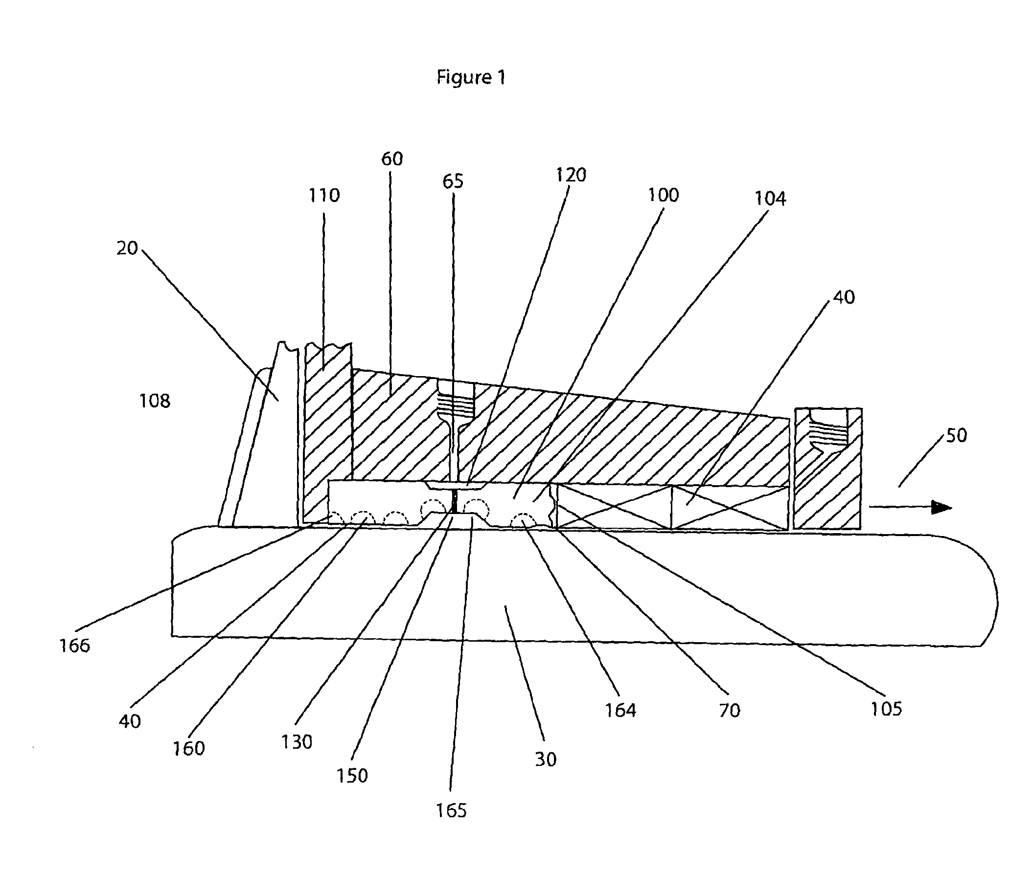
[0047] Bushing 100 has a seal portion 104 adapted to surround the shaft and to engage a seal 40, and an open portion 108 adapted to surround the shaft and to define with the shaft a passageway for ingress and egress of material. Bushing 100 has an outer surface 110 with a circumferential indentation 120, into which a bore 65 through shaft housing 60 empties. Bushing 100 further has a bore 130 which runs from outer surface 110 ...


PUM


Abstract

Rotary shaft (220), housing (250) and packaging type seal (230) together form seal cavity (260). Seal cavity throat protector (200) in cavity (260) protects seal (230) against damaging materials from the region of impeller (210). Such material is directed away from seal (230) along spiral groove(s) (280) on inner surface of protector (200) with the assistance of flushing fluid entering cavity (260) via bore (270) and passing to inner surface of protector (200) via radial bores therethrough.

Description

[0001] The invention relates to seal cavity throat protectors for use with rotary fluid equipment.[0002] In this specification, where a document, act or item of knowledge is referred to or discussed, this reference or discussion is not an admission that the document, act or item of knowledge or any combination thereof was at the priority date:[0003] (i) part of common general knowledge; or[0004] (ii) known to be relevant to an attempt to solve any problem with which this specification is concerned.[0005] Rotary fluid equipment usually includes an operative portion such as an impeller which is driven by a prime mover such as a motor. The operative portion usually has a rotating shaft which connects the prime mover to the operative portion. Typically the operative portion is within a housing and the shaft extends through the back of the housing and through a shaft housing. Usually the shaft will be supported by bearings which are between the prime mover and the operative portion.[0006...

Claims


Application Information

Patent Timeline
IPC IPC(8): F04D29/10F16J15/18
CPCF16J15/182F04D29/106
Inventor PRINZ, WILHELM
Owner PRINZ GMBH & CO KG
Why Eureka
Try Eureka