Tuning screw assembly

a technology of tuning screw and assembly, which is applied in the direction of screws, threaded fasteners, bolts, etc., can solve the problems of not being able to not being able to enable a long axial movement of the screw, and not being able to achieve the frictionally lock a relatively long screw, etc., to achieve the cost-effective way of manufacturing the screw described in the u.s. patent specification, and achieve the effect o

Inactive Publication Date: 2004-02-12
INTEL CORP
View PDF99 Cites 13 Cited by
  • Summary
  • Abstract
  • Description
  • Claims
  • Application Information

AI Technical Summary

Problems solved by technology

This way of securing the tuning screw is rather time consuming and, therefore, some alternative ways of locking such a screw have been provided.
A drawback with the frictionally locking device as described in said U.S. patent (as far as it can be understood from the specification) is that it may not be possible to fri...

Method used


Image

  • Tuning screw assembly
  • Tuning screw assembly
  • Tuning screw assembly

Examples


Embodiment Construction

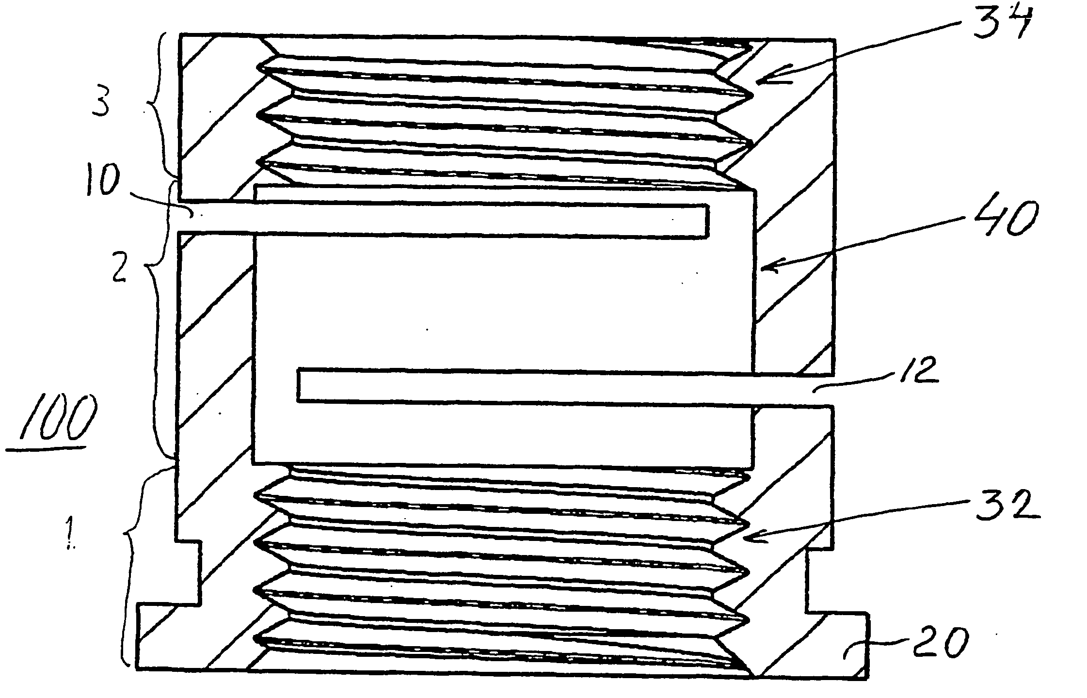
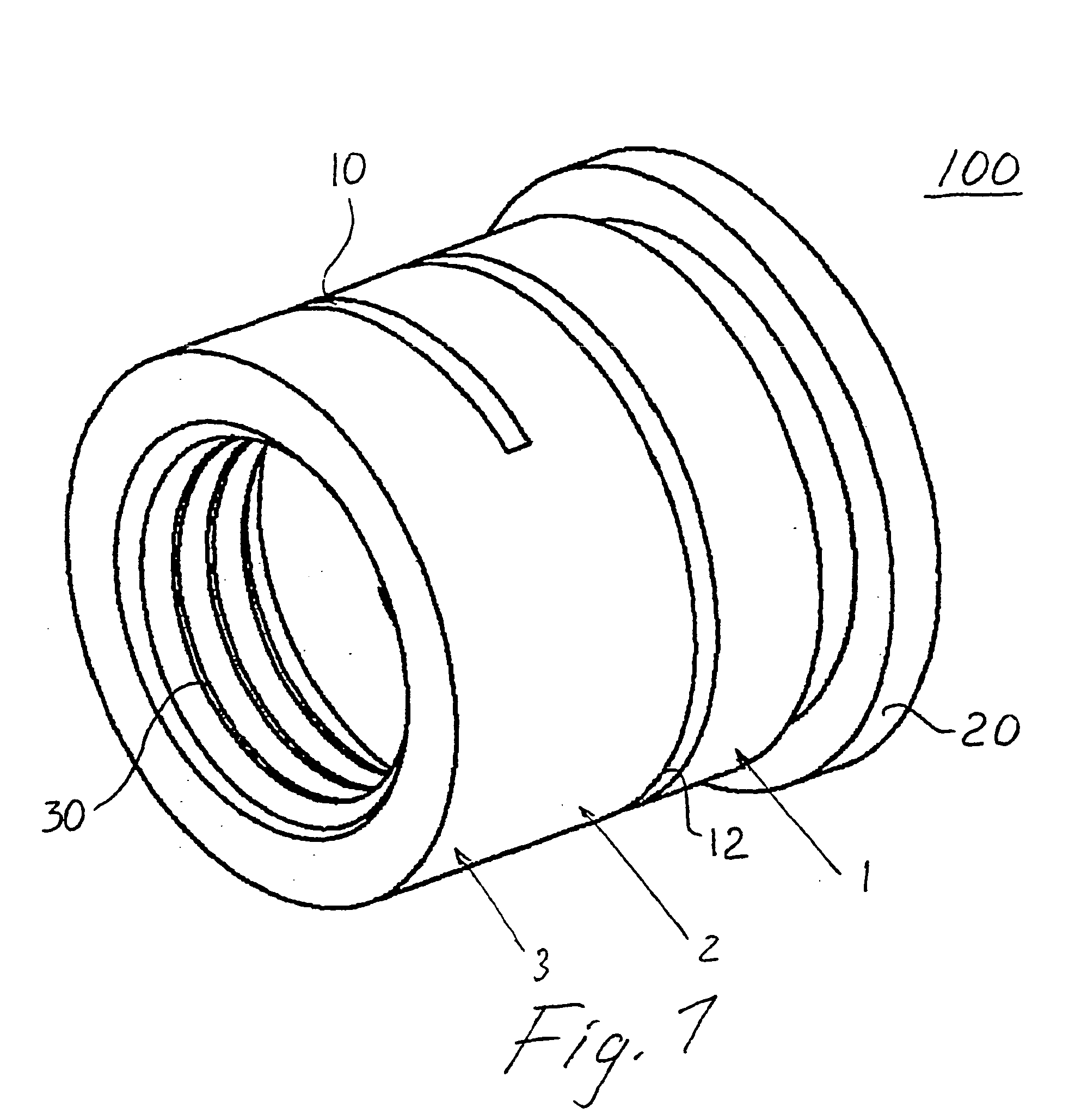
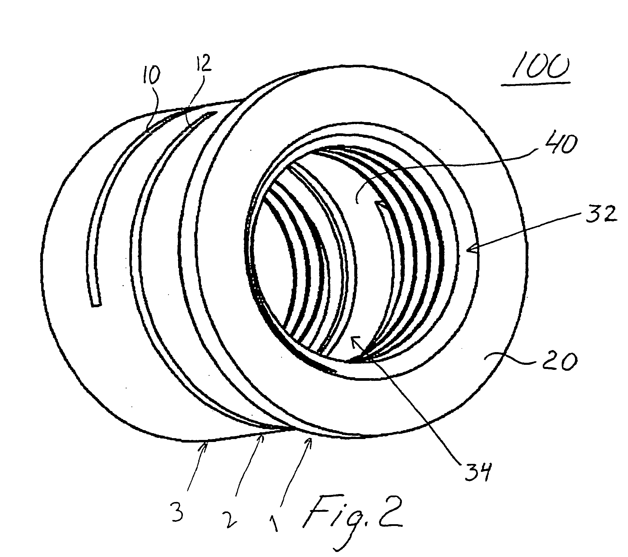
[0024] In accordance with the present invention, a cylindrical sleeve is provided with two axially displaced, internally threaded portions which engage with the external thread of a tuning screw so as to effect frictional locking thereof and electrical coupling in high frequency applications.

[0025] FIG. 1 and 2 show two different perspective views of a sleeve 100, forming part of a tuning screw assembly 100,200 (shown in FIGS. 7 and 8) according to the invention, before being deformed in a direction parallel to its central axis. The sleeve 100 comprises a first axial part 1, an intermediate axial part 2 and a second axial part 3. A first slot 10 and a second slot 12 are located in said intermediate axial part 2. There is an optional flange 20 in said first axial part 1. Internally, threads 30 are provided, including a first threaded portion 32 in said first axial part 1 and a second threaded portion 34 in said second axial part 3, and there is an unthreaded portion 40 in said interm...


PUM


Abstract

The present invention relates to a tuning screw assembly comprising a sleeve (100) with internal threads for engaging a tuning screw (200) having external threads. The sleeve comprises a first threaded portion (32) which is axially displaced in relation to a second threaded portion (34) for frictionally locking said screw body in said sleeve. The invention also relates to a method of manufacturing said friction locking sleeve and to a resonator comprising said friction locking sleeve.

Description

[0001] The present invention relates to a tuning screw assembly, to a method of manufacturing said tuning screw assembly and to a resonator comprising said tuning screw assembly.DESCRIPTION OF THE RELATED ART[0002] In many applications there is a need for mounting a tuning screw with the ability to later on easily adjust the position of the tuning screw. For example, in dielectric resonators, a commonly used method is to secure the tuning screw by using an ordinary locking nut which is tightened to an adjacent surface. This way of securing the tuning screw is rather time consuming and, therefore, some alternative ways of locking such a screw have been provided.[0003] In U.S. Pat. No. 4,305,113, there is described a screw body forming a rotary part of a capacitor including an outer sleeve forming a hollow cylindrical stationary part of the capacitor. The massive screw body has externally threaded portions. These external threaded portions are axially separated by an unthreaded interm...

Claims


Application Information

Patent Timeline
IPC IPC(8): F16B39/284H01P1/00H01P7/04H03J1/00
CPCF16B39/284H03J1/00H01P7/04H01P1/00
Inventor HARALDSSON, TONYOSTIN, JOAKIMLOWENBORG, CLAES-GORAN
Owner INTEL CORP
Why Eureka
Try Eureka